52:
36:
20:
44:
71:
213:
filed a broad patent covering essentially all electromechanical delay lines, but focusing on acoustic delay lines where an air column confined to a pipe served as the mechanical medium, and a telephone receiver at one end and a telephone transmitter at the other end served as the electromechanical
279:
filed a patent for such a line that year. Other GE employees, John Rubel and Roy Troell, concluded that the insulated wire could be wound around a conducting core to achieve the same effect. Much of the development of delay lines during World War II was motivated by the problems encountered in
141:
can also provide a delay element. The delay time of an analog delay line may be only a few nanoseconds or several milliseconds, limited by the practical size of the physical medium used to delay the signal and the propagation speed of impulses in the medium.
274:
By 1943, compact delay lines with distributed capacitance and inductance were devised. Typical early designs involved winding an enamel insulated wire on an insulating core and then surrounding that with a grounded conductive jacket. Richard Nelson of
333:. Arlenberg developed the idea of complex 2- and 3-dimensional folding of the acoustic path in the solid medium in order to package long delays into a compact crystal. The delay lines used to decode
218:
on long-distance telephone lines, and his patent clearly explained the fundamental relationship between inductor–capacitor ladder networks and mechanical elastic delay lines such as his acoustic line.
263:
to use delay lines in his 1939 patent application. He used "delay cables" for this, relatively short pieces of coaxial cable used as delay lines, but he recognized the possibility of using
165:
used an analog delay line to allow observation of waveforms just before some triggering event. Radar systems used liquid delay lines to compare one pulse of radio to another, and after
176:
With the growing use of digital signal processing techniques, digital forms of delay are practical and eliminate some of the problems with dissipation and noise in analog systems.
233:, with a 10 MHz carrier frequency, with multiple baffles and reflectors in the delay tank to create a long acoustic path in a relatively small tank.
194:
were used as analog delay lines in the 1920s. For example, Francis
Hubbard's sonar direction finder patent filed in 1921. Hubbard referred to this as an
608:
51:
291:
delay lines. He recommended their use for applications requiring delays or measurement of intervals in the 10 to 1000 microseconds time range.
47:
Schematic of circuit connections to the acoustic delay line used in NBS mercury memory (top); block diagram of the mercury memory system (bottom)
103:
195:
110:
varies continuously. In the case of a periodic signal, the time difference can be described in terms of a change in the
59:
210:
202:
filed for a patent on a compact packaging of an inductor–capacitor ladder network that he explicitly referred to as a
28:
303:
613:
295:
226:
199:
102:, where each individual element creates a time difference between its input and output. It operates on analog
27:) from a color TV-set. Made of enamelled copper wire, wound in one layer around a copper tube and forming a
252:
365:
130:
115:
256:
95:
240:
applied electromechanical delay lines to the problem of creating artificial reverberation for his
350:
99:
91:
360:
355:
299:
154:
138:
294:
In 1945, Gordon D. Forbes and
Herbert Shapiro filed a patent for the mercury delay line with
288:
276:
264:
215:
145:
Analog delay lines are applied in many types of signal processing circuits; for example the
126:
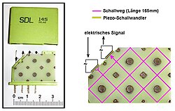
326:
322:
237:
191:
170:
406:
Francis A. Hubbard, System for
Determining the Direction of Propagation of Wave Energy,
298:. This delay line technology would play an important role, serving as the basis of the
35:
602:
386:
321:
in the quartz crystals caused problems. He reported success with single crystals of
310:
268:
241:
158:
111:
338:
166:
162:
221:
In 1938, William
Spencer Percival of Electrical & Musical Industries (later
19:
43:
588:
573:
558:
543:
528:
513:
498:
483:
468:
453:
438:
423:
408:
318:
245:
161:" effect in musical instrument amplifiers, or to simulate an echo. High-speed
134:
122:
188:
107:
451:
William S. Percival, Delay Device for use in
Transmission of Oscillations,
70:
313:
transducers attached to single crystal solid delay lines. He tried using
82:), showing path of sound waves (pink) and transducers (yellow, upper left)
330:
230:
184:
150:
149:
television standard uses an analog delay line to store an entire video
481:
Clarence W. Hansell, Method and Means for
Reducing Multiple Signals,
314:
281:
244:. Hammond used coil springs to transmit mechanical waves between
69:
55:
50:
42:
34:
18:
334:
287:
In 1944, Madison G. Nicholson applied for a general patent on
260:
222:
146:
75:
63:
337:
television signals follow the outline of this patent, using
58:'s ultrasonic mercury delay line memory (capacity: 255
309:
In 1946, David
Arenberg filed patents covering the use of
541:
Gordon D. Forbes and
Herbert Shapiro, Transmission Line,
225:) applied for a patent on an acoustical delay line using
511:
John H. Rubel and Roy E. Troell, Adjustable Delay Line,
114:
of the signal. One example of an analog delay line is a
214:
transducers. Mathes was motivated by the problem of
571:
David L. Arlenberg, Compressional Wave Delay Means,
121:
Other types of delay line include acoustic (usually
133:devices. A series of resistor–capacitor circuits (
496:Richard B. Nelson, Artificial Transmission Line,
526:Madison G. Nicholson Jr., Time Delay Apparatus,
466:Laurens Hammond, Electrical Musical Instrument,
421:Gereld L. Tawney, Electrical Time Delay Line,
8:
436:Robert C. Mathes, Wave Transmission System,
137:) can be cascaded to form a delay. A long
39:A magnetostrictive torsion wire delay line
341:as a medium instead of a single crystal.
377:
229:and a liquid medium. He used water or
29:distributed inductor-capacitor network
586:David L. Arenberg, Solid Delay Line,
7:
317:as a delay medium and reported that
157:delay lines are used to provide a "
14:
385:J. B. Calvert (13 January 2002).
556:David L. Arenberg, Delay Means,
609:Telecommunications engineering
259:motivated Clarence Hansell of
1:
198:. In 1941, Gerald Tawney of
74:Ultrasonic delay line from a
196:Artificial transmission line
251:The problem of suppressing
211:Bell Telephone Laboratories
630:
304:first-generation computers
209:In 1924, Robert Mathes of
296:piezoelectric transducers
227:piezoelectric transducers
577:, granted Apr. 25, 1950.
562:, granted June 20, 1950.
517:, Granted Apr. 19, 1949.
442:, granted Dec. 25, 1928.
427:, Granted Dec. 11, 1945.
412:, Granted Sept. 6, 1927.
200:Sperry Gyroscope Company
592:, granted Jan. 6, 1953.
547:, granted July 1, 1947.
532:, granted May 28, 1946.
502:, granted May 13, 1947.
487:, granted Feb. 9, 1943.
472:, granted Feb. 4, 1941.
387:"Analog Delay Devices"
253:multipath interference
83:
67:
48:
40:
32:
589:U.S. patent 2,624,804
574:U.S. patent 2,505,515
559:U.S. patent 2,512,130
544:U.S. patent 2,423,306
529:U.S. patent 2,401,094
514:U.S. patent 2,467,857
499:U.S. patent 2,420,559
484:U.S. patent 2,310,692
469:U.S. patent 2,230,836
454:U.S. patent 2,263,902
439:U.S. patent 1,696,315
424:U.S. patent 2,390,563
409:U.S. patent 1,641,432
366:Charge-coupled device
131:surface acoustic wave
116:bucket-brigade device
96:electrical components
78:color TV (delay time
73:
54:
46:
38:
23:Electric delay line (
22:
257:television reception
169:these were used as
351:Digital delay line
84:
68:
49:
41:
33:
361:Propagation delay
356:Delay-line memory
300:delay-line memory
155:electromechanical
139:transmission line
88:analog delay line
16:Electronic device
621:
593:
591:
584:
578:
576:
569:
563:
561:
554:
548:
546:
539:
533:
531:
524:
518:
516:
509:
503:
501:
494:
488:
486:
479:
473:
471:
464:
458:
457:, Nov. 25, 1941.
456:
449:
443:
441:
434:
428:
426:
419:
413:
411:
404:
398:
397:
395:
393:
382:
302:used in several
289:magnetostrictive
277:General Electric
265:magnetostrictive
216:echo suppression
127:magnetostrictive
81:
26:
629:
628:
624:
623:
622:
620:
619:
618:
614:Analog circuits
599:
598:
597:
596:
587:
585:
581:
572:
570:
566:
557:
555:
551:
542:
540:
536:
527:
525:
521:
512:
510:
506:
497:
495:
491:
482:
480:
476:
467:
465:
461:
452:
450:
446:
437:
435:
431:
422:
420:
416:
407:
405:
401:
391:
389:
384:
383:
379:
374:
347:
327:sodium chloride
323:lithium bromide
238:Laurens Hammond
204:time delay line
192:ladder networks
182:
171:computer memory
153:. Acoustic and
79:
24:
17:
12:
11:
5:
627:
625:
617:
616:
611:
601:
600:
595:
594:
579:
564:
549:
534:
519:
504:
489:
474:
459:
444:
429:
414:
399:
376:
375:
373:
370:
369:
368:
363:
358:
353:
346:
343:
181:
178:
15:
13:
10:
9:
6:
4:
3:
2:
626:
615:
612:
610:
607:
606:
604:
590:
583:
580:
575:
568:
565:
560:
553:
550:
545:
538:
535:
530:
523:
520:
515:
508:
505:
500:
493:
490:
485:
478:
475:
470:
463:
460:
455:
448:
445:
440:
433:
430:
425:
418:
415:
410:
403:
400:
388:
381:
378:
371:
367:
364:
362:
359:
357:
354:
352:
349:
348:
344:
342:
340:
336:
332:
328:
324:
320:
316:
312:
311:piezoelectric
307:
305:
301:
297:
292:
290:
285:
283:
278:
272:
271:delay lines.
270:
269:piezoelectric
266:
262:
258:
254:
249:
248:transducers.
247:
243:
242:Hammond organ
239:
234:
232:
228:
224:
219:
217:
212:
207:
205:
201:
197:
193:
190:
186:
179:
177:
174:
172:
168:
164:
163:oscilloscopes
160:
159:reverberation
156:
152:
148:
143:
140:
136:
132:
128:
124:
119:
117:
113:
109:
105:
101:
98:connected in
97:
93:
89:
77:
72:
65:
62:= 8,415
61:
57:
53:
45:
37:
30:
21:
582:
567:
552:
537:
522:
507:
492:
477:
462:
447:
432:
417:
402:
390:. Retrieved
380:
339:quartz glass
308:
293:
286:
273:
250:
235:
220:
208:
203:
183:
175:
167:World War II
144:
120:
87:
85:
135:RC circuits
603:Categories
392:28 January
372:References
319:anisotropy
246:voice-coil
123:ultrasonic
284:systems.
236:In 1939,
189:capacitor
173:systems.
108:amplitude
345:See also
331:aluminum
231:kerosene
185:Inductor
151:scanline
180:History
104:signals
100:cascade
92:network
315:quartz
129:, and
106:whose
25:450 ns
282:radar
112:phase
90:is a
80:64 μs
60:words
56:FUJIC
394:2012
329:and
64:bits
335:PAL
267:or
261:RCA
255:in
223:EMI
147:PAL
125:),
94:of
86:An
76:PAL
605::
325:,
306:.
206:.
118:.
396:.
187:–
66:)
31:.
Text is available under the Creative Commons Attribution-ShareAlike License. Additional terms may apply.