511:
combustion zone no longer has to serve as a pressure vessel. The combustion zones can also "communicate" with each other via liner holes or connecting tubes that allow some air to flow circumferentially. The exit flow from the can-annular combustor generally has a more uniform temperature profile, which is better for the turbine section. It also eliminates the need for each chamber to have its own igniter. Once the fire is lit in one or two cans, it can easily spread to and ignite the others. This type of combustor is also lighter than the can type, and has a lower pressure drop (on the order of 6%). However, a can-annular combustor can be more difficult to maintain than a can combustor. Examples of gas turbine engines utilizing a can-annular combustor include the
339:
98:
272:
in a much more even temperature profile, as the cooling air is uniformly introduced through pores. Film cooling air is generally introduced through slats or louvers, resulting in an uneven profile where it is cooler at the slat and warmer between the slats. More importantly, transpiration cooling uses much less cooling air (on the order of 10% of total airflow, rather than 20-50% for film cooling). Using less air for cooling allows more to be used for combustion, which is more and more important for high-performance, high-thrust engines.
563:(DAC). Like an annular combustor, the DAC is a continuous ring without separate combustion zones around the radius. The difference is that the combustor has two combustion zones around the ring; a pilot zone and a main zone. The pilot zone acts like that of a single annular combustor, and is the only zone operating at low power levels. At high power levels, the main zone is used as well, increasing air and mass flow through the combustor. GE's implementation of this type of combustor focuses on reducing
198:
486:
test the whole system). Can-type combustors are easy to maintain, as only a single can needs to be removed, rather than the whole combustion section. Most modern gas turbine engines (particularly for aircraft applications) do not use can combustors, as they often weigh more than alternatives. Additionally, the pressure drop across the can is generally higher than other combustors (on the order of 7%). Most modern engines that use can combustors are
405:
825:) engines present a much different situation for the combustor than conventional gas turbine engines (scramjets are not gas turbines, as they generally have few or no moving parts). While scramjet combustors may be physically quite different from conventional combustors, they face many of the same design challenges, like fuel mixing and flame holding. However, as its name implies, a scramjet combustor must address these challenges in a
503:
538:
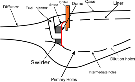
326:(use swirlers). The swirler establishes a local low pressure zone that forces some of the combustion products to recirculate, creating the high turbulence. However, the higher the turbulence, the higher the pressure loss will be for the combustor, so the dome and swirler must be carefully designed so as not to generate more turbulence than is needed to sufficiently mix the fuel and air.
263:. However, air cooling is still required. In general, there are two main types of liner cooling; film cooling and transpiration cooling. Film cooling works by injecting (by one of several methods) cool air from outside of the liner to just inside of the liner. This creates a thin film of cool air that protects the liner, reducing the temperature at the liner from around 1800
469:
547:
shorter size (therefore lighter), and less surface area. Additionally, annular combustors tend to have very uniform exit temperatures. They also have the lowest pressure drop of the three designs (on the order of 5%). The annular design is also simpler, although testing generally requires a full size test rig. An engine that uses an annular combustor is the
391:. The igniter needs to be in the combustion zone where the fuel and air are already mixed, but it needs to be far enough upstream so that it is not damaged by the combustion itself. Once the combustion is initially started by the igniter, it is self-sustaining, and the igniter is no longer used. In can-annular and annular combustors (see
351:
atomizing fuel injectors rely on high fuel pressures (as much as 3,400 kilopascals (500 psi)) to atomize the fuel. This type of fuel injector has the advantage of being very simple, but it has several disadvantages. The fuel system must be robust enough to withstand such high pressures, and the fuel tends to be
779:
rather than a more conventional type. Dump combustors inject fuel and rely on recirculation generated by a large change in area in the combustor (rather than swirlers in many gas turbine combustors). That said, many ramjet combustors are also similar to traditional gas turbine combustors, such as the
635:
Unburned-hydrocarbon (UHC) and carbon-monoxide (CO) emissions are highly related. UHCs are essentially fuel that was not completely combusted. They are mostly produced at low power levels (where the engine is not burning all the fuel). Much of the UHC content reacts and forms CO within the combustor,
546:
The final, and most-commonly used type of combustor is the fully annular combustor. Annular combustors do away with the separate combustion zones and simply have a continuous liner and casing in a ring (the annulus). There are many advantages to annular combustors, including more uniform combustion,
446:
Dilution air is air injected through holes in the liner at the end of the combustion chamber to cool the flue gas before it reaches the turbines. The air is carefully used to produce the uniform temperature profile desired in the combustor. However, as turbine blade technology improves, allowing them
395:
below), the flame can propagate from one combustion zone to another, so igniters are not needed at each one. In some systems ignition-assist techniques are used. One such method is oxygen injection, where oxygen is fed to the ignition area, helping the fuel easily combust. This is particularly useful
374:
The premixing/prevaporizing injectors work by mixing or vaporizing the fuel before it reaches the combustion zone. This method allows the fuel to be very uniformly mixed with the air, reducing emissions from the engine. One disadvantage of this method is that fuel may auto-ignite or otherwise combust
271:
material for the liner. The porous liner allows a small amount of cooling air to pass through it, providing cooling benefits similar to film cooling. The two primary differences are in the resulting temperature profile of the liner and the amount of cooling air required. Transpiration cooling results
184:
below) lifetime by nearly 100 times that of early liners. In the 1980s combustors began to improve their efficiency across the whole operating range; combustors tended to be highly efficient (99%+) at full power, but that efficiency dropped off at lower settings. Development over that decade improved
77:
is fed high-pressure air by the compression system. The combustor then heats this air at constant pressure as the fuel/air mix burns. As it burns the fuel/air mix heats and rapidly expands. The burned mix is exhausted from the combustor through the nozzle guide vanes to the turbine. In the case of a
485:
In most applications, multiple cans are arranged around the central axis of the engine, and their shared exhaust is fed to the turbine(s). Can-type combustors were most widely used in early gas turbine engines, owing to their ease of design and testing (one can test a single can, rather than have to
213:
The case is the outer shell of the combustor, and is a fairly simple structure. The casing generally requires little maintenance. The case is protected from thermal loads by the air flowing in it, so thermal performance is of limited concern. However, the casing serves as a pressure vessel that must
616:
Smoke is primarily mitigated by more evenly mixing the fuel with air. As discussed in the fuel injector section above, modern fuel injectors (such as airblast fuel injectors) evenly atomize the fuel and eliminate local pockets of high fuel concentration. Most modern engines use these types of fuel
481:
Can combustors are self-contained cylindrical combustion chambers. Each "can" has its own fuel injector, igniter, liner, and casing. The primary air from the compressor is guided into each individual can, where it is decelerated, mixed with fuel, and then ignited. The secondary air also comes from
455:
Cooling air is air that is injected through small holes in the liner to generate a layer (film) of cool air to protect the liner from the combustion temperatures. The implementation of cooling air has to be carefully designed so it does not directly interact with the combustion air and process. In
366:
The vaporizing fuel injector, the third type, is similar to the air blast injector in that primary air is mixed with the fuel as it is injected into the combustion zone. However, the fuel-air mixture travels through a tube within the combustion zone. Heat from the combustion zone is transferred to
751:
As with the main combustor in a gas turbine, the afterburner has both a case and a liner, serving the same purpose as their main combustor counterparts. One major difference between a main combustor and an afterburner is that the temperature rise is not constrained by a turbine section, therefore
510:
The next type of combustor is the "can-annular" combustor. Like the can-type combustor, can-annular combustors have discrete combustion zones contained in separate liners with their own fuel injectors. Unlike the can combustor, all the combustion zones share a common ring (annulus) casing. Each
81:
A combustor must contain and maintain stable combustion despite very high air flow rates. To do so combustors are carefully designed to first mix and ignite the air and fuel, and then mix in more air to complete the combustion process. Early gas turbine engines used a single chamber known as a
350:
The fuel injector is responsible for introducing fuel to the combustion zone and, along with the swirler (above), is responsible for mixing the fuel and air. There are four primary types of fuel injectors; pressure-atomizing, air blast, vaporizing, and premix/prevaporizing injectors. Pressure
230:
to a velocity optimal for the combustor. Reducing the velocity results in an unavoidable loss in total pressure, so one of the design challenges is to limit the loss of pressure as much as possible. Furthermore, the diffuser must be designed to limit the flow distortion as much as possible by
167:
Advancements in combustor technology focused on several distinct areas; emissions, operating range, and durability. Early jet engines produced large amounts of smoke, so early combustor advances, in the 1950s, were aimed at reducing the smoke produced by the engine. Once smoke was essentially
774:
engines differ in many ways from traditional gas turbine engines, but most of the same principles hold. One major difference is the lack of rotating machinery (a turbine) after the combustor. The combustor exhaust is directly fed to a nozzle. This allows ramjet combustors to burn at a higher
147:
Wide range of operation. Most combustors must be able to operate with a variety of inlet pressures, temperatures, and mass flows. These factors change with both engine settings and environmental conditions (i.e., full throttle at low altitude can be very different from idle throttle at high
752:
afterburners tend to have a much higher temperature rise than main combustors. Another difference is that afterburners are not designed to mix fuel as well as primary combustors, so not all the fuel is burned within the afterburner section. Afterburners also often require the use of
358:
The second type of fuel injector is the air blast injector. This injector "blasts" a sheet of fuel with a stream of air, atomizing the fuel into homogeneous droplets. This type of fuel injector led to the first smokeless combustors. The air used is just some of the primary air (see
416:
This is the main combustion air. It is highly compressed air from the high-pressure compressor (often decelerated via the diffuser) that is fed through the main channels in the dome of the combustor and the first set of liner holes. This air is mixed with fuel, and then combusted.
666:) are produced in the combustion zone. However, unlike CO, it is most produced during the conditions that CO is most consumed (high temperature, high pressure, long residence time). This means that, in general, reducing CO emissions results in an increase in NO
756:
to keep the velocity of the air in the afterburner from blowing the flame out. These are often bluff bodies or "vee-gutters" directly behind the fuel injectors that create localized low-speed flow in the same manner the dome does in the main combustor.
720:
and combusting it. The advantage of afterburning is significantly increased thrust; the disadvantage is its very high fuel consumption and inefficiency, though this is often regarded as acceptable for the short periods during which it is usually used.
793:
588:
One of the driving factors in modern gas turbine design is reducing emissions, and the combustor is the primary contributor to a gas turbine's emissions. Generally speaking, there are five major types of emissions from gas turbine engines: smoke,
482:
the compressor, where it is fed outside of the liner (inside of which is where the combustion is taking place). The secondary air is then fed, usually through slits in the liner, into the combustion zone to cool the liner via thin film cooling.
655:. This process, which consumes the CO, requires a relatively long time ("relatively" is used because the combustion process happens incredibly quickly), high temperatures, and high pressures. This fact means that a low-CO combustor has a long
636:
which is why the two types of emissions are heavily related. As a result of this close relation, a combustor that is well optimized for CO emissions is inherently well optimized for UHC emissions, so most design work focuses on CO emissions.
143:
Small physical size and weight. Space and weight are at a premium in aircraft applications, so a well designed combustor strives to be compact. Non-aircraft applications, like power-generating gas turbines, are not as constrained by this
456:
some cases, as much as 50% of the inlet air is used as cooling air. There are several different methods of injecting this cooling air, and the method can influence the temperature profile that the liner is exposed to (see
425:
Intermediate air is the air injected into the combustion zone through the second set of liner holes (primary air goes through the first set). This air completes the reaction processes, diluting the high concentrations of
129:
continue to grow more advanced and are able to withstand higher temperatures, the combustors are being designed to burn at higher temperatures and the parts of the combustor need to be designed to withstand those higher
541:
Annular combustor for a gas turbine engine, viewed axis on looking through the exhaust. The small yellow circles are the fuel injection nozzles, while the larger orange ring is the continuous liner for the combustion
115:, and produce a high-velocity gas to exhaust through the nozzle in aircraft applications. As with any engineering challenge, accomplishing this requires balancing many design considerations, such as the following:
1551:
371:, which helps protect the liner. However, the vaporizer tube may have serious durability problems with low fuel flow within it (the fuel inside of the tube protects the tube from the combustion heat).
151:
Environmental emissions. There are strict regulations on aircraft emissions of pollutants like carbon dioxide and nitrogen oxides, so combustors need to be designed to minimize those emissions. (See
125:
The flame (combustion) must be held (contained) inside of the combustor. If combustion happens further back in the engine, the turbine stages can easily be overheated and damaged. Additionally, as
472:
Arrangement of can-type combustors for a gas turbine engine, looking axis on, through the exhaust. Teal color (dark cyan) indicates the cooling-air flow path, orange the combustion gas flow path.
82:
can-type combustor. Today three main configurations exist: can, annular, and cannular (also referred to as can-annular tubo-annular). Afterburners are often considered another type of combustor.
214:
withstand the difference between the high pressures inside the combustor and the lower pressure outside. That mechanical (rather than thermal) load is a driving design factor in the case.
284:
The snout is an extension of the dome (see below) that acts as an air splitter, separating the primary air from the secondary air flows (intermediate, dilution, and cooling air; see
1544:
841:, resulting in loss of thrust, among other problems. To prevent this, scramjet engines tend to have an isolator section (see image) immediately ahead of the combustion zone.
1229:
140:
or other types of damage. Similarly, the temperature profile within the combustor should avoid hot spots, as those can damage or destroy a combustor from the inside.
1537:
119:
Completely combust the fuel. Otherwise, the engine wastes the unburned fuel and creates unwanted emissions of unburned hydrocarbons, carbon monoxide (CO), and soot.
363:
below) that is diverted through the injector, rather than the swirler. This type of injector also requires lower fuel pressures than the pressure atomizing type.
251:
below) into the combustion zone. The liner must be designed and built to withstand extended high-temperature cycles. For that reason liners tend to be made from
872:
has several definitions, in this context it means to form a fine spray. It is not meant to imply that the fuel is being broken down to its atomic components.
1930:
775:
temperature. Another difference is that many ramjet combustors do not use liners like gas turbine combustors do. Furthermore, some ramjet combustors are
551:. Almost all of the modern gas turbine engines use annular combustors; likewise, most combustor research and development focuses on improving this type.
580:. Extending the same principles as the double annular combustor, triple annular and "multiple annular" combustors have been proposed and even patented.
367:
the fuel-air mixture, vaporizing some of the fuel (mixing it better) before it is combusted. This method allows the fuel to be combusted with less
1920:
1893:
1461:
796:
Diagram illustrating a scramjet engine. Notice the isolator section between the compression inlet and combustion chamber. (Illustration from
1427:
1925:
797:
189:. Combustor technology is still being actively researched and advanced, and much modern research focuses on improving the same aspects.
259:. Furthermore, even though high-performance alloys are used, the liners must be cooled with air flow. Some combustors also make use of
1226:
1520:
1499:
1480:
1471:
Henderson, Robert E.; Blazowski, William S. (1989). "Chapter 2: Turbopropulsion
Combustion Technology". In Oates, Gordon C. (ed.).
338:
628:
process, and it is primarily mitigated by reducing fuel usage. On average, 1 kg of jet fuel burned produces 3.2 kg of CO
1793:
1284:
Verkamp, F. J., Verdouw, A. J., Tomlinson, J. G. (1974). Impact of
Emission Regulations on Future Gas Turbine Engine Combustors.
833:
5, the air flow entering the combustor would nominally be Mach 2. One of the major challenges in a scramjet engine is preventing
267:(K) to around 830 K, for example. The other type of liner cooling, transpiration cooling, is a more modern approach that uses a
921:
1395:
122:
Low pressure loss across the combustor. The turbine which the combustor feeds needs high-pressure flow to operate efficiently.
2061:
1842:
1490:
Mattingly, Jack D.; Heiser, William H.; Pratt, David T. (2002). "Chapter 9: Engine
Component Design: Combustion Systems".
632:. Carbon dioxide emissions will continue to drop as manufacturers improve the overall efficiency of gas turbine engines.
180:
section below). The 1970s also saw improvement in combustor durability, as new manufacturing methods improved liner (see
2056:
247:
The liner contains the combustion process and introduces the various airflows (intermediate, dilution, and cooling, see
1163:
Federal
Aviation Administration, FAA-H-8083-32A, Aviation Maintenance Technician Handbook - Powerplant Volume 1, p.1-44
670:, and vice versa. This fact means that most successful emission reductions require the combination of several methods.
1878:
577:
89:, levels of emissions, and transient response (the response to changing conditions such as fuel flow and air speed).
1873:
1649:
97:
1672:
850:
375:
before the fuel-air mixture reaches the combustion zone. If this happens the combustor can be seriously damaged.
235:. Like most other gas turbine engine components, the diffuser is designed to be as short and light as possible.
232:
1950:
1868:
1728:
1822:
1609:
548:
519:
343:
260:
136:
Uniform exit temperature profile. If there are hot spots in the exit flow, the turbine may be subjected to
1798:
1768:
1763:
1687:
1604:
523:
491:
185:
efficiencies at lower levels. The 1990s and 2000s saw a renewed focus on reducing emissions, particularly
2035:
1803:
1773:
1753:
1494:. AIAA Education Series (2nd ed.). Reston, VA: American Institute of Aeronautics and Astronautics.
837:
generated by combustor from traveling upstream into the inlet. If that were to happen, the engine may
447:
to withstand higher temperatures, dilution air is used less, allowing the use of more combustion air.
2066:
2020:
1983:
1935:
1697:
602:
512:
169:
85:
Combustors play a crucial role in determining many of an engine's operating characteristics, such as
621:
197:
1888:
1837:
740:(this is the maximum power the engine can produce); an engine producing maximum thrust dry is at
74:
1915:
1707:
1516:
1495:
1476:
1457:
1449:
701:
368:
1475:. AIAA Education Series. Washington, DC: American Institute of Aeronautics and Astronautics.
2015:
1808:
1778:
1748:
1682:
1419:
1387:
1316:
930:
644:
355:
atomized, resulting in incomplete or uneven combustion which has more pollutants and smoke.
111:
The objective of the combustor in a gas turbine is to add energy to the system to power the
102:
732:
when the engine is used without afterburning. An engine producing maximum thrust wet is at
404:
2030:
1973:
1667:
1595:
1564:
1360:
Stull, F. D. and Craig, R. R. (1975). Investigation of Dump
Combustors with Flameholders.
606:
598:
427:
319:
186:
173:
86:
1515:. AIAA Education Series. Reston, VA: American Institute of Aeronautics and Astronautics.
1124:
1529:
1580:
590:
227:
226:
The purpose of the diffuser is to slow the high-speed, highly compressed, air from the
137:
2050:
1940:
1738:
1712:
1644:
1233:
705:
396:
in some aircraft applications where the engine may have to restart at high altitude.
352:
268:
126:
700:
typical of supersonic aircraft designs means that take-off speed is very high). On
387:
Most igniters in gas turbine applications are electrical spark igniters, similar to
133:
It should be capable of relighting at high altitude in an event of engine flame-out.
1994:
1968:
1958:
1788:
1743:
1413:
753:
697:
537:
502:
1511:
Mattingly, Jack D. (2006). "Chapter 10: Inlets, Nozzles, and
Combustion Systems".
639:
Carbon monoxide is an intermediate product of combustion, and it is eliminated by
1418:. 14th AIAA/AHI Space Planes and Hypersonic Systems and Technologies Conference.
506:
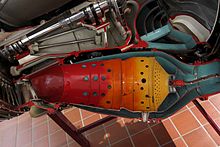
Cannular combustor for a gas turbine engine, viewing axis on, through the exhaust
310:
below) flows through as it enters the combustion zone. Their role is to generate
17:
1863:
1858:
1677:
1575:
1567:
830:
781:
679:
487:
78:
ramjet or scramjet engines, the exhaust is directly fed out through the nozzle.
35:
1376:"History of U.S. Navy Ramjet, Scramjet, and Mixed-Cycle Propulsion Development"
1634:
1560:
1375:
1374:
Waltrup, P.J.; White M.E.; Zarlingo F; Gravlin E. S. (January–February 2002).
1303:
Sturgess, G.J.; Zelina, J.; Shouse D. T.; Roquemore, W.M. (March–April 2005).
1262:
1247:
834:
826:
818:
815:
792:
689:
685:
625:
388:
311:
252:
50:
314:
in the flow to rapidly mix the air with fuel. Early combustors tended to use
306:
The dome and swirler are the part of the combustor that the primary air (see
2025:
1883:
1733:
1629:
1127:. NASA Glenn Research Center. Last Updated 11 Jul 2008. Accessed 6 Jan 2010.
640:
526:
256:
1304:
916:
659:(essentially the amount of time the gases are in the combustion chamber).
468:
168:
eliminated, efforts turned in the 1970s to reducing other emissions, like
1999:
1758:
1702:
1624:
1619:
1600:
810:
805:
709:
652:
515:
431:
105:
43:
1456:. Cambridge Aerospace Series. New York, NY: Cambridge University Press.
1423:
1412:
Goyne, C. P; Hall, C. D.; O'Brian, W. F.; Schetz, J. A (November 2006).
1614:
838:
717:
112:
403:
196:
1783:
1639:
821:
771:
766:
693:
264:
46:
39:
684:
An afterburner (or reheat) is an additional component added to some
1391:
1320:
1305:"Emissions Reduction Technologies for Military Gas Turbine Engines"
934:
1963:
791:
536:
501:
467:
337:
96:
1533:
917:"Gas Turbine Technology Evolution: A Designer's Perspective"
692:
aircraft. Its purpose is to provide a temporary increase in
318:(rather than swirlers), which used a simple plate to create
322:
to mix the fuel and air. Most modern designs, however, are
696:, both for supersonic flight and for takeoff (as the high
438:), and also helps cooling down the gases from combustion.
829:
flow environment. For example, for a scramjet flying at
559:
One variation on the standard annular combustor is the
708:
situations. This is achieved by injecting additional
1415:
The Hy-V Scramjet Flight
Experiment (AIAA 2006-7901)
2008:
1982:
1949:
1906:
1851:
1830:
1821:
1721:
1658:
1588:
1574:
1931:Engine-indicating and crew-alerting system (EICAS)
1227:CFM'S Advanced Double Annular Combustor Technology
1964:Full Authority Digital Engine/Electronics (FADEC)
1473:Aircraft Propulsion Systems Technology and Design
1251:Triple annular combustor for gas turbine engine].
1236:. Press Release. 9 Jul 1998. Accessed 6 Jan 2010.
1513:Elements of Propulsion: Gas Turbines and Rockets
1454:Fundamentals of Jet Propulsion with Applications
1266:Dome assembly for a multiple annular combustor].
578:A good diagram of a DAC is available from Purdue
1364:. Pasadena, CA. 20–22 January 1975. AIAA 75-165
1921:Electronic centralised aircraft monitor (ECAM)
984:
982:
980:
1545:
342:Fuel injectors of a swirl-can combustor on a
8:
1101:
1099:
1014:
1012:
1926:Electronic flight instrument system (EFIS)
1827:
1585:
1552:
1538:
1530:
784:missile, which used a can-type combustor.
1298:
1296:
1294:
1288:. June 1974. Vol. 11, No. 6. pp. 340–344.
1044:
1042:
724:Jet engines are referred to as operating
617:injectors and are essentially smokeless.
27:Part of a jet engine where fuel is burned
1450:"Chapter 9: Combustors and Afterburners"
1172:Mattingly, Heiser, and Pratt, pp. 377–8.
1114:Henderson and Blazowski, pp. 111, 125–7.
997:Mattingly, Heiser, and Pratt, pp. 372–4.
566:
889:
861:
1280:
1278:
1276:
1274:
1272:
712:into the jet pipe downstream of (i.e.
1075:Mattingly, Heiser, and Pratt, p. 368.
1048:Mattingly, Heiser, and Pratt, p. 379.
965:Mattingly, Heiser, and Pratt, p. 375.
956:Mattingly, Heiser, and Pratt, p. 378.
915:Koff, Bernard L. (July–August 2004).
905:Mattingly, Heiser, and Pratt, p. 325.
7:
1362:13th AIAA Aerospace Sciences Meeting
1084:Henderson and Blazowski, pp. 129–30.
947:Henderson and Blazowski, pp. 119–20.
780:combustor in the ramjet used by the
728:when afterburning is being used and
704:the extra thrust is also useful for
1190:Henderson and Blazowski, pp. 106–7.
1006:Henderson and Blazowski, pp. 124–7.
798:The Hy-V Scramjet Flight Experiment
53:takes place. It is also known as a
1245:Ekstedt, Edward E., et al (1994).
25:
1260:Schilling, Jan C., et al (1997).
1794:Thrust specific fuel consumption
1433:from the original on 2007-09-30.
1401:from the original on 2007-04-13.
1199:Henderson and Blazowski, p. 108.
1154:Henderson and Blazowski, p. 106.
1105:Henderson and Blazowski, p. 111.
1093:Henderson and Blazowski, p. 110.
1066:Henderson and Blazowski, p. 129.
1057:Henderson and Blazowski, p. 128.
1036:Henderson and Blazowski, p. 127.
1018:Henderson and Blazowski, p. 124.
974:Henderson and Blazowski, p. 121.
1380:Journal of Propulsion and Power
1309:Journal of Propulsion and Power
922:Journal of Propulsion and Power
69:. In a gas turbine engine, the
1843:Propeller speed reduction unit
688:, primarily those on military
1:
662:Like CO, Nitrogen oxides (NO
34:is a component or area of a
1754:Engine pressure ratio (EPR)
231:avoiding flow effects like
176:(for more details, see the
2083:
2021:Auxiliary power unit (APU)
1650:Rotating detonation engine
803:
764:
677:
1448:Flack, Ronald D. (2005).
851:Components of jet engines
233:boundary layer separation
1729:Aircraft engine starting
561:double annular combustor
555:Double annular combustor
520:Pratt & Whitney JT8D
344:Pratt & Whitney JT9D
261:thermal barrier coatings
1610:Pulse detonation engine
549:CFM International CFM56
492:centrifugal compressors
1799:Thrust to weight ratio
1769:Overall pressure ratio
1764:Jet engine performance
1688:Centrifugal compressor
1605:Gluhareff Pressure Jet
1492:Aircraft Engine Design
801:
543:
507:
473:
408:
389:automotive spark plugs
347:
201:
108:
2062:Jet engine technology
2036:Ice protection system
1804:Variable cycle engine
1774:Propulsive efficiency
1333:Mattingly, pp. 770–1.
1263:U.S. patent 5,630,319
1248:U.S. patent 5,323,604
795:
603:unburned hydrocarbons
540:
505:
471:
407:
341:
200:
170:unburned hydrocarbons
100:
1936:Flight data recorder
1698:Constant speed drive
1678:Afterburner (reheat)
620:Carbon dioxide is a
513:General Electric J79
2057:Combustion chambers
1424:10.2514/6.2006-7901
1286:Journal of Aircraft
393:Types of combustors
1838:Propeller governor
1351:Mattingly, p. 747.
1208:Mattingly, p. 757.
988:Mattingly, p. 760.
802:
544:
508:
474:
409:
348:
202:
109:
75:combustion chamber
63:combustion chamber
2044:
2043:
1916:Annunciator panel
1902:
1901:
1817:
1816:
1708:Propelling nozzle
1463:978-0-521-81983-1
1342:Flack, pp. 445–6.
1181:Flack, pp. 442–4.
1145:Flack, pp. 442–3.
702:military aircraft
369:thermal radiation
18:Annular combustor
16:(Redirected from
2074:
2031:Hydraulic system
2026:Bleed air system
2016:Air-start system
1879:Counter-rotating
1828:
1809:Windmill restart
1779:Specific impulse
1749:Compressor stall
1683:Axial compressor
1586:
1554:
1547:
1540:
1531:
1526:
1505:
1486:
1467:
1435:
1434:
1432:
1409:
1403:
1402:
1400:
1371:
1365:
1358:
1352:
1349:
1343:
1340:
1334:
1331:
1325:
1324:
1300:
1289:
1282:
1267:
1265:
1258:
1252:
1250:
1243:
1237:
1224:
1218:
1215:
1209:
1206:
1200:
1197:
1191:
1188:
1182:
1179:
1173:
1170:
1164:
1161:
1155:
1152:
1146:
1143:
1137:
1134:
1128:
1125:Combustor-Burner
1121:
1115:
1112:
1106:
1103:
1094:
1091:
1085:
1082:
1076:
1073:
1067:
1064:
1058:
1055:
1049:
1046:
1037:
1034:
1028:
1025:
1019:
1016:
1007:
1004:
998:
995:
989:
986:
975:
972:
966:
963:
957:
954:
948:
945:
939:
938:
912:
906:
903:
897:
894:
873:
866:
647:react to form CO
571:
421:Intermediate air
383:
382:
334:
333:
324:swirl stabilized
316:bluff body domes
302:
301:
296:
295:
288:section below).
280:
279:
243:
242:
222:
221:
209:
208:
103:Rolls-Royce Nene
21:
2082:
2081:
2077:
2076:
2075:
2073:
2072:
2071:
2047:
2046:
2045:
2040:
2004:
1987:
1978:
1974:Thrust reversal
1951:Engine controls
1945:
1908:
1898:
1874:Contra-rotating
1847:
1813:
1717:
1668:Accessory drive
1660:
1654:
1596:Air turborocket
1578:
1570:
1558:
1523:
1510:
1502:
1489:
1483:
1470:
1464:
1447:
1439:
1438:
1430:
1411:
1410:
1406:
1398:
1373:
1372:
1368:
1359:
1355:
1350:
1346:
1341:
1337:
1332:
1328:
1302:
1301:
1292:
1283:
1270:
1261:
1259:
1255:
1246:
1244:
1240:
1225:
1221:
1216:
1212:
1207:
1203:
1198:
1194:
1189:
1185:
1180:
1176:
1171:
1167:
1162:
1158:
1153:
1149:
1144:
1140:
1135:
1131:
1122:
1118:
1113:
1109:
1104:
1097:
1092:
1088:
1083:
1079:
1074:
1070:
1065:
1061:
1056:
1052:
1047:
1040:
1035:
1031:
1026:
1022:
1017:
1010:
1005:
1001:
996:
992:
987:
978:
973:
969:
964:
960:
955:
951:
946:
942:
914:
913:
909:
904:
900:
895:
891:
881:
876:
867:
863:
859:
847:
808:
790:
777:dump combustors
769:
763:
682:
676:
669:
665:
650:
631:
612:
607:nitrogen oxides
599:carbon monoxide
596:
586:
575:
570:
564:
557:
535:
524:Rolls-Royce Tay
500:
479:
466:
437:
428:carbon monoxide
402:
380:
379:
353:heterogeneously
331:
330:
320:wake turbulence
299:
298:
293:
292:
277:
276:
240:
239:
219:
218:
206:
205:
195:
187:nitrogen oxides
174:carbon monoxide
165:
101:Combustor on a
95:
87:fuel efficiency
28:
23:
22:
15:
12:
11:
5:
2080:
2078:
2070:
2069:
2064:
2059:
2049:
2048:
2042:
2041:
2039:
2038:
2033:
2028:
2023:
2018:
2012:
2010:
2006:
2005:
2003:
2002:
1997:
1991:
1989:
1980:
1979:
1977:
1976:
1971:
1966:
1961:
1955:
1953:
1947:
1946:
1944:
1943:
1938:
1933:
1928:
1923:
1918:
1912:
1910:
1904:
1903:
1900:
1899:
1897:
1896:
1894:Variable-pitch
1891:
1886:
1881:
1876:
1871:
1869:Constant-speed
1866:
1861:
1855:
1853:
1849:
1848:
1846:
1845:
1840:
1834:
1832:
1825:
1819:
1818:
1815:
1814:
1812:
1811:
1806:
1801:
1796:
1791:
1786:
1781:
1776:
1771:
1766:
1761:
1756:
1751:
1746:
1741:
1736:
1731:
1725:
1723:
1719:
1718:
1716:
1715:
1710:
1705:
1700:
1695:
1690:
1685:
1680:
1675:
1670:
1664:
1662:
1656:
1655:
1653:
1652:
1647:
1642:
1637:
1632:
1627:
1622:
1617:
1612:
1607:
1598:
1592:
1590:
1583:
1581:jet propulsion
1572:
1571:
1559:
1557:
1556:
1549:
1542:
1534:
1528:
1527:
1521:
1507:
1506:
1500:
1487:
1481:
1468:
1462:
1444:
1443:
1437:
1436:
1404:
1392:10.2514/2.5928
1366:
1353:
1344:
1335:
1326:
1321:10.2514/1.6528
1315:(2): 193–217.
1290:
1268:
1253:
1238:
1232:2012-07-28 at
1219:
1217:Flack, p. 444.
1210:
1201:
1192:
1183:
1174:
1165:
1156:
1147:
1138:
1136:Flack, p. 442.
1129:
1116:
1107:
1095:
1086:
1077:
1068:
1059:
1050:
1038:
1029:
1027:Flack, p. 441.
1020:
1008:
999:
990:
976:
967:
958:
949:
940:
935:10.2514/1.4361
929:(4): 577–595.
907:
898:
896:Flack, p. 440.
888:
887:
886:
885:
880:
877:
875:
874:
860:
858:
855:
854:
853:
846:
843:
804:Main article:
789:
786:
765:Main article:
762:
759:
742:military power
678:Main article:
675:
672:
667:
663:
657:residence time
648:
629:
610:
594:
591:carbon dioxide
585:
582:
573:
556:
553:
534:
531:
499:
496:
478:
475:
465:
462:
453:
452:
444:
443:
435:
423:
422:
414:
413:
401:
400:Air flow paths
398:
385:
384:
361:Air flow paths
336:
335:
308:Air flow paths
304:
303:
286:Air flow paths
282:
281:
249:Air flow paths
245:
244:
224:
223:
211:
210:
194:
191:
164:
161:
157:
156:
155:section below)
149:
145:
141:
138:thermal stress
134:
131:
127:turbine blades
123:
120:
94:
91:
26:
24:
14:
13:
10:
9:
6:
4:
3:
2:
2079:
2068:
2065:
2063:
2060:
2058:
2055:
2054:
2052:
2037:
2034:
2032:
2029:
2027:
2024:
2022:
2019:
2017:
2014:
2013:
2011:
2009:Other systems
2007:
2001:
1998:
1996:
1993:
1992:
1990:
1986:and induction
1985:
1981:
1975:
1972:
1970:
1967:
1965:
1962:
1960:
1957:
1956:
1954:
1952:
1948:
1942:
1941:Glass cockpit
1939:
1937:
1934:
1932:
1929:
1927:
1924:
1922:
1919:
1917:
1914:
1913:
1911:
1905:
1895:
1892:
1890:
1887:
1885:
1882:
1880:
1877:
1875:
1872:
1870:
1867:
1865:
1862:
1860:
1857:
1856:
1854:
1850:
1844:
1841:
1839:
1836:
1835:
1833:
1829:
1826:
1824:
1820:
1810:
1807:
1805:
1802:
1800:
1797:
1795:
1792:
1790:
1787:
1785:
1782:
1780:
1777:
1775:
1772:
1770:
1767:
1765:
1762:
1760:
1757:
1755:
1752:
1750:
1747:
1745:
1742:
1740:
1739:Brayton cycle
1737:
1735:
1732:
1730:
1727:
1726:
1724:
1720:
1714:
1713:Turbine blade
1711:
1709:
1706:
1704:
1701:
1699:
1696:
1694:
1691:
1689:
1686:
1684:
1681:
1679:
1676:
1674:
1671:
1669:
1666:
1665:
1663:
1657:
1651:
1648:
1646:
1643:
1641:
1638:
1636:
1633:
1631:
1628:
1626:
1623:
1621:
1618:
1616:
1613:
1611:
1608:
1606:
1602:
1599:
1597:
1594:
1593:
1591:
1587:
1584:
1582:
1577:
1573:
1569:
1566:
1562:
1555:
1550:
1548:
1543:
1541:
1536:
1535:
1532:
1524:
1522:1-56347-779-3
1518:
1514:
1509:
1508:
1503:
1501:1-56347-538-3
1497:
1493:
1488:
1484:
1482:0-930403-24-X
1478:
1474:
1469:
1465:
1459:
1455:
1451:
1446:
1445:
1441:
1440:
1429:
1425:
1421:
1417:
1416:
1408:
1405:
1397:
1393:
1389:
1385:
1381:
1377:
1370:
1367:
1363:
1357:
1354:
1348:
1345:
1339:
1336:
1330:
1327:
1322:
1318:
1314:
1310:
1306:
1299:
1297:
1295:
1291:
1287:
1281:
1279:
1277:
1275:
1273:
1269:
1264:
1257:
1254:
1249:
1242:
1239:
1235:
1234:archive.today
1231:
1228:
1223:
1220:
1214:
1211:
1205:
1202:
1196:
1193:
1187:
1184:
1178:
1175:
1169:
1166:
1160:
1157:
1151:
1148:
1142:
1139:
1133:
1130:
1126:
1123:Benson, Tom.
1120:
1117:
1111:
1108:
1102:
1100:
1096:
1090:
1087:
1081:
1078:
1072:
1069:
1063:
1060:
1054:
1051:
1045:
1043:
1039:
1033:
1030:
1024:
1021:
1015:
1013:
1009:
1003:
1000:
994:
991:
985:
983:
981:
977:
971:
968:
962:
959:
953:
950:
944:
941:
936:
932:
928:
924:
923:
918:
911:
908:
902:
899:
893:
890:
883:
882:
878:
871:
865:
862:
856:
852:
849:
848:
844:
842:
840:
836:
832:
828:
824:
823:
820:
817:
812:
807:
799:
794:
787:
785:
783:
778:
773:
768:
760:
758:
755:
749:
747:
743:
739:
735:
734:maximum power
731:
727:
722:
719:
715:
711:
707:
703:
699:
695:
691:
687:
681:
673:
671:
660:
658:
654:
646:
642:
637:
633:
627:
623:
618:
614:
608:
604:
600:
592:
583:
581:
579:
569:
562:
554:
552:
550:
539:
532:
530:
528:
525:
521:
517:
514:
504:
497:
495:
493:
489:
483:
476:
470:
463:
461:
459:
450:
449:
448:
441:
440:
439:
433:
429:
420:
419:
418:
411:
410:
406:
399:
397:
394:
390:
378:
377:
376:
372:
370:
364:
362:
356:
354:
345:
340:
332:Fuel injector
329:
328:
327:
325:
321:
317:
313:
309:
291:
290:
289:
287:
275:
274:
273:
270:
266:
262:
258:
254:
250:
238:
237:
236:
234:
229:
217:
216:
215:
204:
203:
199:
192:
190:
188:
183:
179:
175:
171:
162:
160:
154:
150:
146:
142:
139:
135:
132:
130:temperatures.
128:
124:
121:
118:
117:
116:
114:
107:
104:
99:
92:
90:
88:
83:
79:
76:
72:
68:
64:
60:
56:
52:
48:
45:
41:
37:
33:
19:
1995:Flame holder
1969:Thrust lever
1959:Autothrottle
1789:Thrust lapse
1744:Bypass ratio
1692:
1576:Gas turbines
1568:gas turbines
1512:
1491:
1472:
1453:
1442:Bibliography
1414:
1407:
1386:(1): 14–27.
1383:
1379:
1369:
1361:
1356:
1347:
1338:
1329:
1312:
1308:
1285:
1256:
1241:
1222:
1213:
1204:
1195:
1186:
1177:
1168:
1159:
1150:
1141:
1132:
1119:
1110:
1089:
1080:
1071:
1062:
1053:
1032:
1023:
1002:
993:
970:
961:
952:
943:
926:
920:
910:
901:
892:
869:
864:
814:
809:
776:
770:
754:flameholders
750:
745:
741:
737:
733:
729:
725:
723:
713:
698:wing loading
683:
674:Afterburners
661:
656:
638:
634:
619:
615:
587:
567:
560:
558:
545:
509:
484:
480:
457:
454:
445:
442:Dilution air
424:
415:
392:
386:
373:
365:
360:
357:
349:
323:
315:
307:
305:
285:
283:
248:
246:
225:
212:
181:
177:
166:
158:
152:
110:
93:Fundamentals
84:
80:
70:
67:flame holder
66:
62:
58:
54:
31:
29:
2067:Jet engines
1909:instruments
1864:Blade pitch
1859:Autofeather
1561:Jet engines
835:shock waves
782:RIM-8 Talos
686:jet engines
680:Afterburner
605:(UHC), and
576:emissions.
498:Can-annular
488:turboshafts
451:Cooling air
412:Primary air
257:Hastelloy X
253:superalloys
36:gas turbine
2051:Categories
1852:Principles
1831:Components
1823:Propellers
1722:Principles
1673:Air intake
1661:components
1659:Mechanical
1635:Turboshaft
879:References
827:supersonic
819:combustion
816:supersonic
738:max reheat
690:supersonic
626:combustion
490:featuring
460:, above).
312:turbulence
228:compressor
193:Components
182:Components
148:altitude).
59:burner can
51:combustion
1884:Proprotor
1734:Bleed air
1693:Combustor
1630:Turboprop
788:Scramjets
643:. CO and
641:oxidation
584:Emissions
527:turbofans
430:(CO) and
178:Emissions
159:Sources:
153:Emissions
71:combustor
32:combustor
2000:Jet fuel
1889:Scimitar
1759:Flameout
1703:Impeller
1625:Turbojet
1620:Turbofan
1601:Pulsejet
1565:aircraft
1428:Archived
1396:Archived
1230:Archived
845:See also
811:Scramjet
806:Scramjet
518:and the
516:turbojet
432:hydrogen
346:turbofan
220:Diffuser
113:turbines
106:turbojet
44:scramjet
1988:systems
1615:Propfan
870:atomize
839:unstart
761:Ramjets
746:max dry
718:turbine
624:of the
622:product
533:Annular
381:Igniter
300:swirler
265:kelvins
163:History
144:factor.
1907:Engine
1784:Thrust
1645:Rocket
1640:Ramjet
1519:
1498:
1479:
1460:
868:While
822:ramjet
772:Ramjet
767:Ramjet
716:) the
706:combat
694:thrust
601:(CO),
572:and CO
269:porous
55:burner
49:where
47:engine
40:ramjet
1589:Types
1431:(PDF)
1399:(PDF)
884:Notes
857:Notes
714:after
542:zone.
464:Types
458:Liner
278:Snout
255:like
241:Liner
42:, or
1984:Fuel
1579:and
1563:and
1517:ISBN
1496:ISBN
1477:ISBN
1458:ISBN
831:Mach
710:fuel
651:and
522:and
294:Dome
207:Case
172:and
1420:doi
1388:doi
1317:doi
931:doi
744:or
736:or
730:dry
726:wet
613:).
609:(NO
597:),
593:(CO
477:Can
73:or
65:or
2053::
1452:.
1426:.
1394:.
1384:18
1382:.
1378:.
1313:21
1311:.
1307:.
1293:^
1271:^
1098:^
1041:^
1011:^
979:^
927:20
925:.
919:.
800:.)
748:.
645:OH
565:NO
529:.
494:.
434:(H
297:/
61:,
57:,
38:,
30:A
1603:/
1553:e
1546:t
1539:v
1525:.
1504:.
1485:.
1466:.
1422::
1390::
1323:.
1319::
937:.
933::
813:(
668:x
664:x
653:H
649:2
630:2
611:x
595:2
574:2
568:x
436:2
20:)
Text is available under the Creative Commons Attribution-ShareAlike License. Additional terms may apply.