345:, with the 90 Hz output pulling the needle right and the other left. Along the centreline the two modulating tones of the sidebands will be cancelled out and both voltages will be zero, leaving the needle centered in the display. If the aircraft is far to the left, the 90 Hz signal will produce a strong DC voltage (predominates), and the 150 Hz signal is minimised, pulling the needle all the way to the right. This means the voltmeter directly displays both the direction and magnitude of the turn needed to bring the aircraft back to the runway centreline. As the measurement compares different parts of a single signal entirely in electronics, it provides angular resolution of less than a degree, and allows the construction of a
1314:
modernization and in all-weather operations capability at CATI/II and III airports, terminal area navigation, missed approach guidance and surface operations. GBAS provides the capability to service the entire airport with a single frequency (VHF transmission) whereas ILS requires a separate frequency for each runway end. GBAS CAT-I is seen as a necessary step towards the more stringent operations of CAT-II/III precision approach and landing. The technical risk of implementing GBAS delayed widespread acceptance of the technology. The FAA, along with industry, have fielded
Provably Safe Prototype GBAS stations that mitigate the impact of satellite signal deformation, ionosphere differential error, ephemeris error, and multipath.
705:
691:). Most often, these are at larger airports but many small general aviation airports in the U.S. have approach lights to support their ILS installations and obtain low-visibility minimums. The ALS assists the pilot in transitioning from instrument to visual flight, and to align the aircraft visually with the runway centerline. Pilot observation of the approach lighting system at the Decision Altitude allows the pilot to continue descending towards the runway, even if the runway or runway lights cannot be seen, since the ALS counts as runway end environment. In the U.S., an ILS without approach lights may have CAT I ILS visibility minimums as low as
92:
325:, the antenna is normally placed centrally at the far end of the runway and consists of multiple antennas in an array normally about the width of the runway. Each individual antenna has a particular phase shift and power level applied only to the SBO signal such that the resulting signal is retarded 90 degrees on the left side of the runway and advanced 90 degrees on the right. Additionally, the 150 Hz signal is inverted on one side of the pattern, another 180 degree shift. Due to the way the signals mix in
672:
1039:(SMGCS) plan. Operations below 600 ft RVR require taxiway centerline lights and taxiway red stop bar lights. If the CAT IIIb RVR minimums on a runway end are 600 feet (180 m), which is a common figure in the U.S., ILS approaches to that runway end with RVR below 600 feet (180 m) qualify as CAT IIIc and require special taxi procedures, lighting, and approval conditions to permit the landings. FAA Order 8400.13D limits CAT III to 300 ft RVR or better. Order 8400.13D (2009) allows
386:
transmitted using lower carrier frequencies, using 40 selected channels between 108.10 MHz and 111.95 MHz, whereas the glideslope has a corresponding set of 40 channels between 328.6 and 335.4 MHz. The higher frequencies generally result in the glideslope radiating antennas being smaller. The channel pairs are not linear; localizer channel 1 is at 108.10 and paired with glideslope at 334.70, whereas channel two is 108.15 and 334.55. There are gaps and jumps through both bands.
287:, used a more complex system of signals and an antenna array to achieve higher accuracy. This requires significantly more complexity in the ground station and transmitters, with the advantage that the signals can be accurately decoded in the aircraft using simple electronics and displayed directly on analog instruments. The instruments can be placed in front of the pilot, eliminating the need for a radio operator to continually monitor the signals and relay the results to the pilot over the
390:
310:, secondary frequencies that are created when two different signals are mixed. For instance, if one takes a radio frequency signal at 10 MHz and mixes that with an audible tone at 2500 Hz, four signals will be produced, at the original signals' frequencies of 2500 and 10000000 hertz, and sidebands 9997500 and 10002500 hertz. The original 2500 Hz signal's frequency is too low to travel far from an antenna, but the other three signals are all
1047:
system is considered as fail-operational. A HUD allows the flight crew to fly the aircraft using the guidance cues from the ILS sensors such that if a safe landing is in doubt, the crew can respond in an appropriate and timely manner. HUD is becoming increasingly popular with "feeder" airlines and most manufacturers of regional jets are now offering HUDs as either standard or optional equipment. A HUD can provide capability to take off in low visibility.
370:
2352:
483:
596:. This lets aircraft land using the signal transmitted from the back of the localizer array. Highly directional antennas do not provide a sufficient signal to support a back course. In the United States, back course approaches are typically associated with Category I systems at smaller airports that do not have an ILS on both ends of the primary runway. Pilots flying a back course should disregard any glide slope indication.
444:
209:
38:
2609:
1145:
2619:
306:. In the earlier beam systems, the signal was turned on and off entirely, corresponding to a modulation index of 100%. The determination of angle within the beam is based on the comparison of the audible strength of the two signals. sa In ILS, a more complex system of signals and antennas varies the modulation of two signals across the entire width of the beam pattern. The system relies on the use of
515:
terrain is sloping or uneven, reflections can create an uneven glidepath, causing unwanted needle deflections. Additionally, since the ILS signals are pointed in one direction by the positioning of the arrays, glide slope supports only straight-line approaches with a constant angle of descent. Installation of an ILS can be costly because of siting criteria and the complexity of the antenna system.
1051:
378:
directional signals, which demanded that they be relatively narrow. The ILS pattern can be much wider. ILS installations are normally required to be usable within 10 degrees on either side of the runway centerline at 25 nautical miles (46 km; 29 mi), and 35 degrees on either side at 17 nautical miles (31 km; 20 mi). This allows for a wide variety of approach paths.
1011:
1373:
498:
1287:(GNSS) resulted in its not being adopted in civil aviation. At the time ILS and MLS were the only standardized systems in Civil Aviation that meet requirements for Category III automated landings. The first Category III MLS for civil aviation was commissioned at Heathrow airport in March 2009 and removed from service in 2017.
2076:
2013:
Sep 24, 1929: At
Mitchel Field, N.Y., Army Lt. James H. Doolittle became the first pilot to use only instrument guidance to take off, fly a set course, and land. Doolittle received directional guidance from a radio range course aligned with the airport runway, while radio marker beacons indicated his
1085:
For both automatic and HUD landing systems, the equipment requires special approval for its design and also for each individual installation. The design takes into consideration additional safety requirements for operating an aircraft close to the ground and the ability of the flight crew to react to
1046:
In each case, a suitably equipped aircraft and appropriately qualified crew are required. For example, CAT IIIb requires a fail-operational system, along with a crew who are qualified and current, while CAT I does not. A HUD that allows the pilot to perform aircraft maneuvers rather than an automatic
1001:
An ILS must shut down upon internal detection of a fault condition. Higher categories require shorter response times; therefore, ILS equipment is required to shut down more quickly. For example, a CAT I localizer must shut down within 10 seconds of detecting a fault, but a CAT III localizer must shut
993:
Smaller aircraft generally are equipped to fly only a CAT I ILS. On larger aircraft, these approaches typically are controlled by the flight control system with the flight crew providing supervision. CAT I relies only on altimeter indications for decision height, whereas CAT II and CAT III approaches
737:
mile (600 m) visibility 1,800-foot (550 m) visual range is possible if the runway has high-intensity edge lights, touchdown zone and centerline lights, and an ALS that is at least 2,400 feet (730 m) long (see Table 3-3-1 "Minimum visibility values" in FAA Order 8260.3C). In effect, ALS
618:
of 75 MHz are provided. When the transmission from a marker beacon is received it activates an indicator on the pilot's instrument panel and the tone of the beacon is audible to the pilot. The distance from the runway at which this indication should be received is published in the documentation
377:
Additionally, because it is the encoding of the signal within the beam that contains the angle information, not the strength of the beam, the signal does not have to be tightly focussed in space. In the older beam systems, the accuracy of the equisignal area was a function of the pattern of the two
333:
A receiver in front of the array will receive both of these signals mixed together. Using simple electronic filters, the original carrier and two sidebands can be separated and demodulated to extract the original amplitude-modulated 90 and 150 Hz signals. These are then averaged to produce two
317:
ILS starts by mixing two modulating signals to the carrier, one at 90 Hz and another at 150. This creates a signal with five radio frequencies in total, the carrier and four sidebands. This combined signal, known as the CSB for "carrier and sidebands", is sent out evenly from an antenna array.
1313:
in the United States) is a safety-critical system that augments the GNSS Standard
Positioning Service (SPS) and provides enhanced levels of service. It supports all phases of approach, landing, departure, and surface operations within the VHF coverage volume. GBAS is expected to play a key role in
1101:
will direct aircraft to the localizer course via assigned headings, making sure aircraft do not get too close to each other (maintain separation), but also avoiding delay as much as possible. Several aircraft can be on the ILS at the same time, several miles apart. An aircraft that has turned onto
1021:
In contrast to other operations, CAT III weather minima do not provide sufficient visual references to allow a manual landing to be made. CAT IIIb minima depend on roll-out control and redundancy of the autopilot, because they give only enough time for the pilot to decide whether the aircraft will
514:
Due to the complexity of ILS localizer and glide slope systems, there are some limitations. Localizer systems are sensitive to obstructions in the signal broadcast area, such as large buildings or hangars. Glide slope systems are also limited by the terrain in front of the glide slope antennas. If
505:
The pilot controls the aircraft so that the glide slope indicator remains centered on the display to ensure the aircraft is following the glide path of approximately 3° above horizontal (ground level) to remain above obstructions and reach the runway at the proper touchdown point (i.e. it provides
754:
Once established on an approach, the pilot follows the ILS approach path indicated by the localizer and descends along the glide path to the decision height. This is the height at which the pilot must have adequate visual reference to the landing environment (e.g. approach or runway lighting) to
644:
measurement of distance to the runway. DMEs are augmenting or replacing markers in many installations. The DME provides more accurate and continuous monitoring of correct progress on the ILS glide slope to the pilot, and does not require an installation outside the airport boundary. When used in
1334:
Local Area
Augmentation System (LAAS) is under development to provide for Category III minimums or lower. The FAA Ground-Based Augmentation System (GBAS) office is currently working with the industry in anticipation of the certification of the first GBAS ground stations in Memphis, TN; Sydney,
579:
It is essential that any failure of the ILS to provide safe guidance be detected immediately by the pilot. To achieve this, monitors continually assess the vital characteristics of the transmissions. If any significant deviation beyond strict limits is detected, either the ILS is automatically
1026:
is mandatory to perform
Category III operations. Its reliability must be sufficient to control the aircraft to touchdown in CAT IIIa operations and through rollout to a safe taxi speed in CAT IIIb (and CAT IIIc when authorized). However, special approval has been granted to some operators for
274:
Accuracy of the system was normally on the order of 3 degrees in azimuth. While this was useful for bringing the aircraft onto the direction of the runway, it was not accurate enough to safely bring the aircraft to visual range in bad weather; the radio course beams were used only for lateral
266:
To use the system an aircraft only needed a conventional radio receiver. As they approached the airport they would tune in the signal and listen to it in their headphones. They would hear dots and dashes (Morse code "A" or "N"), if they were to the side of the runway, or if they were properly
1034:
In the United States, airports with CAT III approaches have listings for CAT IIIa and IIIb or just CAT III on the instrument approach plate (U.S. Terminal
Procedures). CAT IIIb RVR minimums are limited by the runway/taxiway lighting and support facilities, and are consistent with the airport
385:
works in the same general fashion as the localizer and uses the same encoding, but is normally transmitted to produce a centerline at an angle of 3 degrees above horizontal from an antenna beside the runway instead of the end. The only difference between the signals is that the localizer is
570:
transmits IJFK to identify itself, while runway 4L is known as IHIQ. This lets users know the facility is operating normally and that they are tuned to the correct ILS. The glide slope station transmits no identification signal, so ILS equipment relies on the localizer for identification.
329:
the SBO signals destructively interfere with and almost eliminate each other along the centerline, leaving the CSB signal predominating. At any other location, on either side of the centerline, the SBO and CSB signals combine in different ways so that one modulating signal predominates.
1662:
738:
extends the runway environment out towards the landing aircraft and allows low-visibility operations. CAT II and III ILS approaches generally require complex high-intensity approach light systems, while medium-intensity systems are usually paired with CAT I ILS approaches. At some
397:
Many illustrations of the ILS concept often show the system operating more similarly to beam systems with the 90 Hz signal on one side and the 150 on the other. These illustrations are inaccurate; both signals are radiated across the entire beam pattern, it is their relative
262:
dots and dashes. The switch also controlled which of two directional antennae the signal was sent to. The resulting signal sent into the air consists of dots sent to one side of the runway and dashes to the other. The beams were wide enough so they overlapped in the center.
87:
can be made. Other versions of the system, or "categories", have further reduced the minimum altitudes, runway visual ranges (RVRs), and transmitter and monitoring configurations designed depending on the normal expected weather patterns and airport safety requirements.
338:(DC) signals. Each of these signals represents not the strength of the original signal, but the strength of the modulation relative to the carrier, which varies across the beam pattern. This has the great advantage that the measurement of angle is independent of range.
1168:" after its inventor, the C. Lorenz AG company. The Civil Aeronautics Board (CAB) of the United States authorized installation of the system in 1941 at six locations. The first landing of a scheduled U.S. passenger airliner using ILS was on January 26, 1938, when a
2073:
521:
and ILS sensitive areas are established to avoid hazardous reflections that would affect the radiated signal. The location of these critical areas can prevent aircraft from using certain taxiways leading to delays in takeoffs, increased hold times, and increased
759:
procedure, then try the same approach again, try a different approach, or divert to another airport. Usually, the decision on whether or not the pilot continues with the approach relies on whether the runway is visible or not, or if the runway is clear or not.
1279:(MLS) allowed for curved approaches. It was introduced in the 1970s to replace ILS but fell out of favor because of the introduction of satellite based systems. In the 1980s, there was a major US and European effort to establish MLS. But a combination of
352:
Although the encoding scheme is complex, and requires a considerable amount of ground equipment, the resulting signal is both far more accurate than the older beam-based systems and is far more resistant to common forms of interference. For instance,
1077:
based on infrared sensors, that provide a day-like visual environment and allow operations in conditions and at airports that would otherwise not be suitable for a landing. Commercial aircraft also frequently use such equipment for takeoffs when
1338:
The
Honeywell and FAA team obtained System Design Approval of the world's first non-federal U.S. approval for LAAS Category I at Newark Liberty International Airport, operations in September 2009 and Operational Approval on September 28, 2012.
1327:(GPS) provides an alternative source of approach guidance for aircraft. In the US, the Wide Area Augmentation System (WAAS) has been available in many regions to provide precision guidance to Category I standards since 2007. The equivalent
1331:(EGNOS) was certified for use in safety of life applications in March 2011. As such, the number of Cat I ILS installations may be reduced, however there are no plans in the United States to phase out any Cat II or Cat III systems.
2074:
https://www.marketwatch.com/press-release/instrument-landing-systemsils-market-share-size-global-regional-analysis-key-findings-growth-factors-industry-demand-key-players-profiles-future-prospects-and-forecasts-to-2025-2021-08-26
195:
signal to be broadcast from the airport, which is dramatically less expensive than the multiple, large and powerful transmitters required for a full ILS implementation. By 2015, the number of US airports supporting ILS-like
1786:
365:
effects due to the use of multiple frequencies, but because those effects are dependent on the terrain, they are generally fixed in location and can be accounted for through adjustments in the antenna or phase shifters.
619:
for that approach, together with the height at which the aircraft should be if correctly established on the ILS. This provides a check on the correct function of the glide slope. In modern ILS installations, a
580:
switched off or the navigation and identification components are removed from the carrier. Either of these actions will activate an indication ('failure flag') on the instruments of an aircraft using the ILS.
2319:
1697:
1031:(HUD) guidance that provides the pilot with an image viewed through the windshield with eyes focused at infinity, of necessary electronic guidance to land the airplane with no true outside visual references.
1191:
The instrument landing systems market revenue was US$ 1,215 million in 2019, and is expected to reach US$ 1,667 million in 2025, with a CAGR of 5.41% during 2020–2025 even with the negative effects of the
2184:
2126:
318:
The CSB is also sent into a circuit that suppresses the original carrier, leaving only the four sideband signals. This signal, known as SBO for "sidebands only", is also sent to the antenna array.
357:
in the signal will affect both sub-signals equally, so it will have no effect on the result. Similarly, changes in overall signal strength as the aircraft approaches the runway, or changes due to
275:
guidance, and the system was not enough on its own to perform landings in heavy rain or fog. Nevertheless, the final decision to land was made at only 300 metres (980 ft) from the airport.
191:(GNSSs) instead of requiring expensive airport infrastructure is leading to the replacement of ILS. Providing the required accuracy with GNSS normally requires only a low-power omnidirectional
2508:
271:. The accuracy of this measurement was highly dependent on the skill of the operator, who listened to the signal on earphones in a noisy aircraft, often while communicating with the tower.
1065:
Some commercial aircraft are equipped with automatic landing systems that allow the aircraft to land without transitioning from instruments to visual conditions for a normal landing. Such
2068:
Instrument
Landing Systems(Ils) Market Share, Size Global Regional Analysis, Key Findings, Growth Factors, Industry Demand, Key Players Profiles, Future Prospects and Forecasts to 2025 (
727:
mile (0.80 km) (runway visual range of 2,400 feet (730 m)) are possible with a CAT I ILS approach supported by a 1,400-to-3,000-foot-long (430 to 910 m) ALS, and
1335:
Australia; Bremen, Germany; Spain; and Newark, NJ. All four countries have installed GBAS ground stations and are involved in technical and operational evaluation activities.
1303:(WAAS), LPV has similar minima to ILS for appropriately equipped aircraft. As of November 2008, the FAA has published more LPV approaches than Category I ILS procedures.
1940:
145:(DME). The ILS usually includes high-intensity lighting at the end of the runways to help the pilot locate the runway and transition from the approach to a visual landing.
746:; for example, the pilot can key the microphone seven times to turn on the lights on the high intensity, five times to medium intensity or three times for low intensity.
2504:
1328:
1069:
operations require specialized equipment, procedures and training, and involve the aircraft, airport, and the crew. Autoland is the only way some major airports such as
429:
to fly the approach automatically. An ILS consists of two independent sub-systems. The localizer provides lateral guidance; the glide slope provides vertical guidance.
1102:
the inbound heading and is within two and a half degrees of the localizer course (half scale deflection or less shown by the course deviation indicator) is said to be
550:
2290:- Illustrates and describes how ILS navigation signals are displayed on board of an aircraft in various positions, which may occur during a safe approach for landing.
425:
An aircraft approaching a runway is guided by the ILS receivers in the aircraft by performing modulation depth comparisons. Many aircraft can route signals into the
562:
In addition to the previously mentioned navigational signals, the localizer provides for ILS facility identification by periodically transmitting a 1,020 Hz
2191:
2130:
1466:
1296:
197:
99:, which provides lateral guidance. The transmitter and antenna are on the centerline at the opposite end of the runway from the approach threshold. Photo of
1684:
2683:
2341:
2047:
1852:
2351:
649:
modified so that one unit can provide distance information to either runway threshold. For approaches where a DME is specified in lieu of marker beacons,
2512:
2215:
1043:
approaches to runways without ALSF-2 approach lights and/or touchdown zone/centerline lights, which has expanded the number of potential CAT II runways.
959:
150 ft (46 m) allowed by FAA with RVR > 1,400 ft (430 m), CAT II aircraft and crew, CAT II/III HUD and CAT II/III missed approach.
1086:
a system anomaly. The equipment also has additional maintenance requirements to ensure that it is capable of supporting reduced visibility operations.
2240:
165:
653:
is noted on the instrument approach procedure and the aircraft must have at least one operating DME unit, or an IFR-approved system using a GNSS (an
2663:
1812:
2673:
1564:
539:(LDA) in the United States) – a modified ILS to accommodate a non-straight approach; the most famous example was for the approach to runway 13 at
468:
The localizer will allow the aircraft to turn and match the aircraft with the runway. After that, the pilots will activate approach phase (APP).
1620:
623:
is installed, co-located with the ILS, to augment or replace marker beacons. A DME continuously displays the aircraft's distance to the runway.
119:(329.15 to 335 MHz frequency) for vertical guidance. The relationship between the aircraft's position and these signals is displayed on an
1714:
1386:
1175:
D flew from
Washington, D.C., to Pittsburgh, Pennsylvania, and landed in a snowstorm using only the Instrument Landing System. The first fully
69:
at night or in bad weather. In its original form, it allows an aircraft to approach until it is 200 feet (61 m) over the ground, within a
701:
mile (1.2 km) (runway visual range of 4,000 feet (1,200 m)) if the required obstacle clearance surfaces are clear of obstructions.
567:
399:
704:
2556:
477:
258:
systems of various types. These normally consisted of a radio transmitter that was connected to a motorized switch to produce a pattern of
233:
361:, will have little effect on the resulting measurement because they would normally affect both channels equally. The system is subject to
2283:
2552:
438:
188:
2014:
distance from the runway. He flew in a hooded cockpit, but was accompanied by a check pilot who could have intervened in an emergency.
1284:
709:
2653:
2025:
1754:
1548:
156:. The US-developed SCS-51 system was more accurate while also adding vertical guidance. Many sets were installed at airbases in the
1117:(a carryover from when an analog meter movement indicated deviation from the course line via voltages sent from the ILS receiver).
986:
ICAO/FAA only, not mentioned by the JAA(EASA), not used on airports by May 2017, a plane would have to be towed to clear the runway
200:
approaches exceeded the number of ILS installations, and this is expected to lead to the eventual removal of ILS at most airports.
1976:
1951:
1169:
523:
2528:
2496:
2334:
2144:
2480:
2448:
2396:
1460:
1310:
536:
2108:
1884:
91:
2259:
1518:
1300:
232:, using a combination of radio signals and, in many cases, high-intensity lighting arrays to enable a safe landing during
1218:
1132:
where the autopilot or Flight
Control Computer directly flies the aircraft and the flight crew monitor the operation, or
465:
normally located beyond the departure end of the runway and generally consists of several pairs of directional antennas.
2540:
2488:
2484:
1415:
1404:
1022:
land in the touchdown zone (basically CAT IIIa) and to ensure safety during rollout (basically CAT IIIb). Therefore, an
646:
637:
632:
620:
487:
142:
141:(MM), placed close to the position of the (CAT 1) decision height. Markers are largely being phased out and replaced by
83:. Bringing the aircraft this close to the runway dramatically increases the range of weather conditions in which a safe
79:
mile (800 m) of the runway. At that point the runway should be visible to the pilot; if it is not, they perform a
2612:
1998:
Repository and Open Science Access Portal; National Transportation Library; United States Department of Transportation
127:. The pilot attempts to manoeuvre the aircraft to keep the indicators centered while they approach the runway to the
2648:
2524:
2492:
2476:
2460:
2388:
2327:
1500:
1426:
1363:
1290:
1114:
173:
31:
1910:
1208:
675:
645:
conjunction with an ILS, the DME is often sited midway between the reciprocal runway thresholds with the internal
2668:
2643:
2428:
1680:
1512:
1443:
1324:
1089:
Nearly all of this pilot training and qualification work is done in simulators with various degrees of fidelity.
1070:
743:
2253:
2039:
1859:
2622:
2596:
1489:
1477:
1276:
1161:
1106:
on the approach. Typically, an aircraft is established by at least 2 nautical miles (3.7 km) prior to the
684:
666:
592:. However, usage of older, less directional antennas allows a runway to have a non-precision approach called a
177:
1243:
1160:
alone, without a view outside the cockpit. A basic system, fully operative, was introduced in 1932 at Berlin-
2520:
1454:
1136:
where the flight crew flies the aircraft manually to keep the localizer and glideslope indicators centered.
1125:
518:
415:
2678:
2576:
2468:
1483:
1437:
1036:
671:
1779:
2516:
2360:
2293:
1809:
1641:
369:
362:
2234:
414:') is published for each ILS approach to provide the information needed to fly an ILS approach during
2588:
2500:
2472:
2456:
2404:
2400:
1975:
For example, Southwest Airlines flies HUD equipped Boeing 737 aircraft to fog-prone airports such as
299:
2001:
1718:
2436:
2432:
2424:
2384:
1506:
1098:
947:
782:
739:
589:
221:
180:(MLS), but few of these systems have been deployed. ILS remains a widespread standard to this day.
2618:
2572:
2444:
2420:
2412:
1228:
1157:
1107:
393:
Common type of illustration showing misleading examples of ILS localizer and glideslope emissions
346:
184:
124:
120:
148:
A number of radio-based landing systems were developed between the 1920s and 1940s, notably the
2300:
2658:
2580:
2280:
2209:
1544:
1306:
1193:
1144:
615:
303:
192:
1990:
2464:
1495:
1343:
1253:
448:
419:
389:
326:
295:
58:
2102:"Annex 10 – Aeronautical Telecommunications, Volume I (Radio Navigation Aids) Amendment 81"
2564:
2287:
2080:
1816:
1731:
1449:
1377:
1153:
1121:
1074:
1028:
995:
777:
756:
540:
459:
311:
237:
164:, which led to it being selected as the international standard after the formation of the
128:
80:
1747:
755:
decide whether to continue the descent to a landing; otherwise, the pilot must execute a
103:
localizer, taken at the runway 06L of the Montréal–Trudeau International Airport, Canada.
2026:"Planes Are Landing By Radio When Fog Hides The Field", February 1931, Popular Mechanics
968:
1,200 ft (370 m) RVR in Canada, 2,600 ft (790 m) RVR for single crew
482:
2584:
2380:
2376:
2127:"Worlds first low-visibility microwave landing system comes into operation at Heathrow"
1263:
1113:
Aircraft deviation from the optimal path is indicated to the flight crew by means of a
443:
411:
335:
157:
100:
37:
2637:
2560:
2536:
2392:
2356:
1832:
1014:
611:
605:
168:(ICAO) in 1947. Several competing landing systems have been developed, including the
133:
17:
2148:
1810:
FAA Order 8260.3C, United States Standard for Terminal Instrument Procedures (TERPS)
2544:
2452:
2440:
2416:
2408:
1248:
1120:
The output from the ILS receiver goes to the display system (head-down display and
462:
284:
208:
161:
153:
108:
1979:(KSMF), allowing flights to take off when they would otherwise be unable to do so.
2101:
1991:"FAA Historical Chronology: Civil Aviation and the Federal Government, 1926–1996"
1073:
remain operational every day of the year. Some modern aircraft are equipped with
418:
operations. A chart includes the radio frequencies used by the ILS components or
2592:
2091:
Microwave Landing System For Jets Is Demonstrated. New York Times. May 20, 1976.
2069:
1888:
1472:
1293:(TLS) can be used where a conventional ILS cannot work or is not cost-effective.
1213:
1180:
1165:
641:
354:
249:
149:
1050:
2568:
1172:
563:
259:
1941:"Acceptable Means of Compliance (AMC) and Guidance Material (GM) to Part-SPA"
115:(108 to 112 MHz frequency), which provides horizontal guidance, and the
1238:
1233:
1010:
544:
501:
Given this display, the pilot must correct to the left and a little upwards.
426:
342:
96:
2170:
1585:
1746:
Department of Transportation and Department of Defense (March 25, 2002).
1399:
1391:
1351:
1176:
1066:
1058:
1023:
307:
288:
225:
62:
46:
2231:
ICAO Annex 10 Volume 1, Radio Navigation Aids, Fifth Edition — July 1996
2275:
2265:
1928:
Aeronautical Telecommunications, Volume 1 (Radio Navigation Aids) 2.1.1
1280:
1204:
The top 10 manufacturers in the instrument landing systems market are:
1054:
491:
452:
84:
497:
402:
that changes dependent upon the position of the approaching aircraft.
1347:
1156:
becoming the first pilot to take off, fly and land an airplane using
358:
229:
137:
provide distance information as the approach proceeds, including the
66:
224:
system that provides precision lateral and vertical guidance to an
2532:
1421:
1143:
1049:
1009:
703:
670:
496:
481:
442:
388:
207:
169:
36:
1410:
654:
2323:
2301:"New Instrument System Proposed for Flight and Landing Safety"
1432:
769:
ICAO/FAA/JAA (EASA) precision instrument approach and landing
657:
system meeting TSO-C129/ -C145/-C146), to begin the approach.
267:
aligned, the two mixed together to produce a steady tone, the
2270:
566:
identification signal. For example, the ILS for runway 4R at
254:
Previous blind landing radio aids typically took the form of
2509:
Satellite emergency position-indicating radiobeacon station
1223:
458:
A localizer (LOC, or LLZ until ICAO standardisation) is an
2145:"EGNOS navigation system begins serving Europe's aircraft"
1152:
Tests of the ILS began in 1929 in the United States, with
2000:. United States Federal Aviation Administration. p.
240:
or reduced visibility due to fog, rain, or blowing snow.
553:(ICLS) – a modified ILS for (aircraft) carrier landing.
1621:"An Introduction into the Signals of ILS, DME and VOR"
950:
has an unusually high glideslope angle of 5.5 degrees.
41:
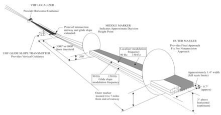
Diagram of an instrument landing system (ILS) approach
2260:"Happy Landings In Fog", June 1933, Popular Mechanics
1361:
1017:
indicating the ILS category of a runway as CAT II/III
683:
Some installations include medium- or high-intensity
422:
and the prescribed minimum visibility requirements.
2367:
1833:"Getting to grips with CAT II / CAT III operations"
341:The two DC signals are then sent to a conventional
1110:(glideslope intercept at the specified altitude).
2505:Emergency position-indicating radiobeacon station
1329:European Geostationary Navigation Overlay Service
152:which saw relatively wide use in Europe prior to
1916:. Transport Canada. March 31, 2016. p. 282.
1847:
1845:
294:Key to its operation is a concept known as the
1827:
1825:
1128:. An aircraft landing procedure can be either
283:The ILS, developed just prior to the start of
95:View of the primary component of the ILS, the
2335:
2262:article on the early system setup in the USA.
1715:"Approach chart of Kai Tak Airport runway 13"
1663:"Localizer and Glide slope Frequency Pairing"
61:system that provides short-range guidance to
8:
1858:. IVAO training. 31 May 2017. Archived from
1586:"History of Radio Flight Navigation Systems"
1565:"Satellite Navigation - GPS/WAAS Approaches"
1467:Localizer performance with vertical guidance
1440:– the pilot who made first automated landing
1297:Localizer Performance with Vertical guidance
410:An instrument approach procedure chart (or '
2276:Website dedicated to the description of ILS
1819:, effective 2016-03-14, accessed 2017-12-04
400:difference in the depth of modulation (DDM)
2513:Standard frequency and time signal station
2342:
2328:
2320:
2307:. Vol. 46, no. 1. pp. 86–88
1741:
1739:
234:instrument meteorological conditions (IMC)
977:No touchdown zone, no centerline lighting
166:International Civil Aviation Organization
1037:surface movement guidance control system
767:
447:The localizer station for runway 27R at
368:
90:
1950:. EASA. 25 October 2012. Archived from
1717:. flyingtigersgroup.org. Archived from
1531:
1368:
939:
2256:– U.S. Centennial of Flight Commission
2214:: CS1 maint: archived copy as title (
2207:
1748:"2001 Federal Radionavigation Systems"
1700:ILS Glide Slope Critical Area Advisory
1636:
1634:
1580:
1578:
1576:
1574:
1387:Acronyms and abbreviations in avionics
1027:hand-flown CAT III approaches using a
946:The slope is selected by the airport,
486:Glide slope station for runway 09R at
2050:from the original on 20 February 2014
1614:
1612:
1610:
1608:
1606:
1604:
1602:
1543:(1st ed.). Osprey. p. 143.
1283:reluctance to invest and the rise of
1148:Luftwaffe AFN 2 indicator, built 1943
1006:Special CAT II and CAT III operations
588:Modern localizer antennas are highly
568:John F. Kennedy International Airport
7:
1179:using ILS occurred in March 1964 at
478:Instrument landing system glide path
373:Normal limits of localizer coverage.
314:and can be effectively transmitted.
2355:
2171:"2017 Federal Radionavigation Plan"
1887:. FAA. May 15, 2018. Archived from
1219:Advanced Navigation and Positioning
998:(RA) to determine decision height.
439:Instrument landing system localizer
321:For lateral guidance, known as the
189:global navigation satellite systems
123:, often additional pointers in the
27:Ground-based visual aid for landing
2684:Types of final approach (aviation)
2299:Jackson, Hagan L. (January 1947).
2040:"History of Aircraft Landing Aids"
1853:"Navigation instrumentation – ILS"
1760:from the original on June 14, 2011
1732:Kai Tak Airport#Runway 13 approach
1285:Global Navigation Satellite System
744:pilot controls the lighting system
710:Aurel Vlaicu International Airport
535:Instrument guidance system (IGS) (
25:
2129:. atc-network.com. Archived from
1911:"Aeronautical Information Manual"
551:Instrument carrier landing system
2617:
2608:
2607:
2350:
2254:History of Aircraft Landing Aids
2114:from the original on 2008-10-15.
1687:from the original on 2014-02-23.
1371:
1307:Ground-Based Augmentation System
298:, a measure of how strongly the
30:For the Preston Reed album, see
2664:Navigational flight instruments
2549:Instrument landing system (ILS)
2497:Radio direction-finding station
2359:and systems in accordance with
2235:Aeronautical Information Manual
1948:Annex to ED Decision 2012-019-R
1792:from the original on 2017-02-11
1619:Balmus, Elena (16 April 2019).
2674:Radio stations and systems ITU
2481:Radionavigation mobile station
2449:On-board communication station
2397:High altitude platform station
1461:Local Area Augmentation System
1311:Local Area Augmentation System
1124:if installed) and may go to a
1075:enhanced flight vision systems
537:localizer type directional aid
1:
1704:: pg 4, ILS Course Distortion
1519:Wide Area Augmentation System
1346:based landing system, called
1301:Wide Area Augmentation System
1259:Other manufacturers include:
1170:Pennsylvania Central Airlines
1002:down in less than 2 seconds.
640:(DME) provides pilots with a
416:instrument flight rules (IFR)
228:approaching and landing on a
2529:Ship's emergency transmitter
2489:Radiolocation mobile station
2485:Radionavigation land station
1416:Distance measuring equipment
1405:Blind approach beacon system
1209:Airport Lighting Specialists
1057:view of a CAT IIIa landing (
1041:special authorization CAT II
750:Decision altitude and height
708:Approach lighting system at
638:Distance measuring equipment
633:Distance measuring equipment
143:distance measuring equipment
65:to allow them to approach a
2241:Digital Terminal Procedures
1681:"ICAO DOC8400 Amendment 28"
1642:"Instrument Landing System"
524:separation between aircraft
220:operates as a ground-based
2700:
2525:Experimental radio station
2493:Radiolocation land station
2477:Radiodetermination station
2461:Aeronautical earth station
1501:Transponder landing system
1350:, is in operation on some
1291:Transponder Landing System
812:ft) or visibility > 800
664:
630:
603:
475:
436:
296:amplitude modulation index
247:
176:(GCA) and the more recent
174:ground-controlled approach
32:Instrument Landing (album)
29:
2603:
2429:Land mobile earth station
2237:, FAA – February 11, 2010
2169:Mattis, James N. (2017).
1513:VHF omnidirectional range
1444:Global Positioning System
1325:Global Positioning System
1162:Tempelhof Central Airport
1097:At a controlled airport,
1071:Charles de Gaulle Airport
678:approach lighting system.
218:instrument landing system
107:ILS uses two directional
51:instrument landing system
2654:Aircraft landing systems
2597:Emergency locator beacon
1977:Sacramento International
1541:A Dictionary of Aviation
1539:Wragg, David W. (1973).
1490:Precision approach radar
1478:Microwave landing system
1277:Microwave Landing System
1164:(Germany) named LFF or "
1024:automatic landing system
667:Approach lighting system
178:microwave landing system
2521:Radio astronomy station
2271:ILS Tutorial Animations
2125:NATS (March 26, 2009).
1989:Preston, Edmund (ed.).
1455:Instrument flight rules
1244:Liberty Airport Systems
1126:Flight Control Computer
717:Visibility minimums of
610:On some installations,
2469:Aircraft earth station
2389:Survival craft station
2281:ILS Tutorial Animation
2044:centennialofflight.net
1484:Non-directional beacon
1438:George Vernon Holloman
1299:(LPV) is based on the
1149:
1062:
1018:
713:
685:approach light systems
679:
502:
494:
455:
394:
374:
213:
204:Principle of operation
104:
42:
2361:ITU Radio Regulations
2294:Categories of the ILS
1930:(incomplete citation)
1352:short runway airports
1147:
1053:
1013:
707:
676:Odate-Noshiro Airport
674:
594:localizer back course
584:Localizer back course
500:
485:
446:
392:
372:
211:
94:
40:
18:Category III approach
2589:Multi-satellite link
2545:Radar beacon (racon)
2501:Radio beacon station
2473:Broadcasting station
2457:Aeronautical station
2405:Mobile earth station
2028:bottom-right of page
740:non-towered airports
506:vertical guidance).
363:multipath distortion
300:amplitude modulation
185:precision approaches
183:The introduction of
2437:Coast earth station
2425:Land mobile station
2377:Terrestrial station
1838:. Airbus. Oct 2001.
1507:Visual flight rules
1264:Indra (Normarc ILS)
1099:air traffic control
948:London City Airport
849:JAA(EASA): > 300
783:Runway visual range
770:
222:instrument approach
121:aircraft instrument
2445:Ship earth station
2421:Base earth station
2413:Land earth station
2286:2016-03-04 at the
2079:2021-09-21 at the
1815:2017-05-13 at the
1323:The advent of the
1229:Universal Avionics
1150:
1108:final approach fix
1063:
1019:
913:JAA(EASA): 250–700
839:ICAO/FAA: > 350
768:
714:
680:
519:ILS critical areas
503:
495:
456:
395:
375:
347:precision approach
302:is applied to the
214:
125:attitude indicator
105:
43:
2649:Navigational aids
2631:
2630:
2581:Satellite network
1891:on March 22, 2022
1194:COVID-19 pandemic
1177:automatic landing
936:
935:
903:ICAO/FAA: 150–700
661:Approach lighting
616:carrier frequency
472:Glide slope (G/S)
304:carrier frequency
57:) is a precision
16:(Redirected from
2691:
2669:Radio navigation
2644:1929 in aviation
2621:
2611:
2610:
2577:Satellite system
2465:Aircraft station
2372:
2354:
2344:
2337:
2330:
2321:
2316:
2314:
2312:
2243:, FAA – May 2010
2220:
2219:
2213:
2205:
2203:
2202:
2196:
2190:. Archived from
2189:
2181:
2175:
2174:
2166:
2160:
2159:
2157:
2156:
2147:. Archived from
2141:
2135:
2134:
2133:on July 7, 2011.
2122:
2116:
2115:
2113:
2106:
2098:
2092:
2089:
2083:
2066:
2060:
2059:
2057:
2055:
2035:
2029:
2023:
2017:
2016:
2010:
2008:
1995:
1986:
1980:
1973:
1967:
1966:
1964:
1962:
1956:
1945:
1937:
1931:
1924:
1918:
1917:
1915:
1907:
1901:
1900:
1898:
1896:
1885:"Order 8400.13D"
1881:
1875:
1874:
1872:
1870:
1864:
1857:
1849:
1840:
1839:
1837:
1829:
1820:
1807:
1801:
1800:
1798:
1797:
1791:
1784:
1776:
1770:
1769:
1767:
1765:
1759:
1752:
1743:
1734:
1729:
1723:
1722:
1711:
1705:
1695:
1689:
1688:
1677:
1671:
1670:
1659:
1653:
1652:
1646:
1638:
1629:
1628:
1616:
1597:
1596:
1590:
1582:
1569:
1568:
1561:
1555:
1554:
1536:
1496:Space modulation
1376:
1375:
1374:
1367:
1254:Rockwell Collins
987:
984:
978:
975:
969:
966:
960:
957:
951:
944:
920:
916:
910:
906:
899:
895:
883:
879:
872:
868:
856:
852:
846:
842:
835:
831:
819:
815:
811:
807:
800:
796:
771:
736:
735:
731:
726:
725:
721:
700:
699:
695:
627:DME substitution
488:Hannover Airport
449:Hannover Airport
134:marker beacon(s)
78:
77:
73:
59:radio navigation
21:
2699:
2698:
2694:
2693:
2692:
2690:
2689:
2688:
2634:
2633:
2632:
2627:
2599:
2565:Radio altimeter
2541:Secondary radar
2517:Amateur station
2370:
2368:
2363:
2348:
2310:
2308:
2298:
2288:Wayback Machine
2250:
2228:
2223:
2206:
2200:
2198:
2194:
2187:
2185:"Archived copy"
2183:
2182:
2178:
2168:
2167:
2163:
2154:
2152:
2143:
2142:
2138:
2124:
2123:
2119:
2111:
2104:
2100:
2099:
2095:
2090:
2086:
2081:Wayback Machine
2067:
2063:
2053:
2051:
2037:
2036:
2032:
2024:
2020:
2006:
2004:
1993:
1988:
1987:
1983:
1974:
1970:
1960:
1958:
1957:on 21 July 2018
1954:
1943:
1939:
1938:
1934:
1925:
1921:
1913:
1909:
1908:
1904:
1894:
1892:
1883:
1882:
1878:
1868:
1866:
1865:on 16 July 2017
1862:
1855:
1851:
1850:
1843:
1835:
1831:
1830:
1823:
1817:Wayback Machine
1808:
1804:
1795:
1793:
1789:
1782:
1778:
1777:
1773:
1763:
1761:
1757:
1750:
1745:
1744:
1737:
1730:
1726:
1713:
1712:
1708:
1696:
1692:
1679:
1678:
1674:
1661:
1660:
1656:
1644:
1640:
1639:
1632:
1618:
1617:
1600:
1595:. pp. 2–4.
1588:
1584:
1583:
1572:
1563:
1562:
1558:
1551:
1538:
1537:
1533:
1529:
1524:
1427:Flight director
1382:
1372:
1370:
1362:
1360:
1321:
1272:
1202:
1189:
1181:Bedford Airport
1154:Jimmy Doolittle
1142:
1122:head-up display
1095:
1029:head-up display
1008:
996:radio altimeter
991:
990:
985:
981:
976:
972:
967:
963:
958:
954:
945:
941:
918:
914:
912:
908:
904:
897:
893:
881:
877:
870:
866:
854:
850:
848:
844:
840:
833:
829:
817:
813:
809:
805:
798:
794:
778:Decision height
766:
757:missed approach
752:
733:
729:
728:
723:
719:
718:
716:
697:
693:
692:
682:
669:
663:
635:
629:
614:operating at a
608:
602:
586:
577:
560:
541:Kai Tak Airport
532:
512:
480:
474:
441:
435:
408:
312:radio frequency
281:
252:
246:
206:
129:decision height
101:Indra's Normarc
81:missed approach
75:
71:
70:
35:
28:
23:
22:
15:
12:
11:
5:
2697:
2695:
2687:
2686:
2681:
2676:
2671:
2666:
2661:
2656:
2651:
2646:
2636:
2635:
2629:
2628:
2626:
2625:
2615:
2604:
2601:
2600:
2585:Satellite link
2583: |
2557:ILS glide path
2487: |
2401:Mobile station
2375:
2373:
2365:
2364:
2357:Radio stations
2349:
2347:
2346:
2339:
2332:
2324:
2318:
2317:
2296:
2291:
2278:
2273:
2268:
2263:
2257:
2249:
2248:External links
2246:
2245:
2244:
2238:
2232:
2227:
2224:
2222:
2221:
2176:
2161:
2136:
2117:
2093:
2084:
2061:
2030:
2018:
1981:
1968:
1932:
1926:ICAO Annex 10
1919:
1902:
1876:
1841:
1821:
1802:
1771:
1735:
1724:
1721:on 2009-03-03.
1706:
1690:
1672:
1654:
1630:
1598:
1570:
1556:
1549:
1530:
1528:
1525:
1523:
1522:
1516:
1510:
1504:
1498:
1493:
1487:
1481:
1475:
1470:
1464:
1458:
1452:
1447:
1441:
1435:
1430:
1424:
1419:
1413:
1408:
1402:
1397:
1394:
1389:
1383:
1381:
1380:
1359:
1356:
1320:
1317:
1316:
1315:
1304:
1294:
1288:
1271:
1268:
1267:
1266:
1257:
1256:
1251:
1246:
1241:
1236:
1231:
1226:
1221:
1216:
1211:
1201:
1198:
1188:
1185:
1141:
1138:
1094:
1091:
1080:takeoff minima
1007:
1004:
989:
988:
979:
970:
961:
952:
938:
937:
934:
933:
930:
927:
923:
922:
901:
890:
886:
885:
874:
863:
859:
858:
837:
826:
822:
821:
802:
791:
787:
786:
780:
775:
765:
764:ILS categories
762:
751:
748:
665:Main article:
662:
659:
631:Main article:
628:
625:
612:marker beacons
604:Main article:
601:
600:Marker beacons
598:
585:
582:
576:
573:
559:
558:Identification
556:
555:
554:
548:
531:
528:
511:
508:
476:Main article:
473:
470:
437:Main article:
434:
431:
412:approach plate
407:
404:
336:direct current
280:
277:
248:Main article:
245:
242:
236:, such as low
205:
202:
158:United Kingdom
26:
24:
14:
13:
10:
9:
6:
4:
3:
2:
2696:
2685:
2682:
2680:
2679:Runway safety
2677:
2675:
2672:
2670:
2667:
2665:
2662:
2660:
2657:
2655:
2652:
2650:
2647:
2645:
2642:
2641:
2639:
2624:
2620:
2616:
2614:
2606:
2605:
2602:
2598:
2595: |
2594:
2591: |
2590:
2587: |
2586:
2582:
2579: |
2578:
2575: |
2574:
2571: |
2570:
2567: |
2566:
2563: |
2562:
2561:Marker beacon
2559: |
2558:
2555: |
2554:
2553:ILS localizer
2551: |
2550:
2547: |
2546:
2543: |
2542:
2539: |
2538:
2537:Primary radar
2535: |
2534:
2531: |
2530:
2527: |
2526:
2523: |
2522:
2519: |
2518:
2515: |
2514:
2511: |
2510:
2507: |
2506:
2503: |
2502:
2499: |
2498:
2495: |
2494:
2491: |
2490:
2486:
2483: |
2482:
2479: |
2478:
2475: |
2474:
2471: |
2470:
2467: |
2466:
2463: |
2462:
2459: |
2458:
2455: |
2454:
2451: |
2450:
2447: |
2446:
2443: |
2442:
2439: |
2438:
2435: |
2434:
2433:Coast station
2431: |
2430:
2427: |
2426:
2423: |
2422:
2419: |
2418:
2415: |
2414:
2411: |
2410:
2407: |
2406:
2403: |
2402:
2399: |
2398:
2395: |
2394:
2393:Fixed station
2391: |
2390:
2387: |
2386:
2385:Space station
2383: |
2382:
2381:Earth station
2379: |
2378:
2374:
2366:
2362:
2358:
2353:
2345:
2340:
2338:
2333:
2331:
2326:
2325:
2322:
2306:
2302:
2297:
2295:
2292:
2289:
2285:
2282:
2279:
2277:
2274:
2272:
2269:
2267:
2264:
2261:
2258:
2255:
2252:
2251:
2247:
2242:
2239:
2236:
2233:
2230:
2229:
2225:
2217:
2211:
2197:on 2014-02-22
2193:
2186:
2180:
2177:
2172:
2165:
2162:
2151:on 2011-03-06
2150:
2146:
2140:
2137:
2132:
2128:
2121:
2118:
2110:
2103:
2097:
2094:
2088:
2085:
2082:
2078:
2075:
2071:
2065:
2062:
2049:
2045:
2041:
2038:Mola, Roger.
2034:
2031:
2027:
2022:
2019:
2015:
2003:
1999:
1992:
1985:
1982:
1978:
1972:
1969:
1953:
1949:
1942:
1936:
1933:
1929:
1923:
1920:
1912:
1906:
1903:
1890:
1886:
1880:
1877:
1861:
1854:
1848:
1846:
1842:
1834:
1828:
1826:
1822:
1818:
1814:
1811:
1806:
1803:
1788:
1781:
1775:
1772:
1756:
1749:
1742:
1740:
1736:
1733:
1728:
1725:
1720:
1716:
1710:
1707:
1703:
1701:
1694:
1691:
1686:
1682:
1676:
1673:
1668:
1664:
1658:
1655:
1650:
1643:
1637:
1635:
1631:
1626:
1622:
1615:
1613:
1611:
1609:
1607:
1605:
1603:
1599:
1594:
1587:
1581:
1579:
1577:
1575:
1571:
1566:
1560:
1557:
1552:
1550:9780850451634
1546:
1542:
1535:
1532:
1526:
1520:
1517:
1514:
1511:
1508:
1505:
1502:
1499:
1497:
1494:
1491:
1488:
1485:
1482:
1479:
1476:
1474:
1471:
1468:
1465:
1462:
1459:
1456:
1453:
1451:
1448:
1445:
1442:
1439:
1436:
1434:
1431:
1428:
1425:
1423:
1420:
1417:
1414:
1412:
1409:
1406:
1403:
1401:
1398:
1395:
1393:
1390:
1388:
1385:
1384:
1379:
1369:
1365:
1357:
1355:
1353:
1349:
1345:
1342:In Norway, a
1340:
1336:
1332:
1330:
1326:
1318:
1312:
1308:
1305:
1302:
1298:
1295:
1292:
1289:
1286:
1282:
1278:
1274:
1273:
1269:
1265:
1262:
1261:
1260:
1255:
1252:
1250:
1247:
1245:
1242:
1240:
1237:
1235:
1232:
1230:
1227:
1225:
1222:
1220:
1217:
1215:
1212:
1210:
1207:
1206:
1205:
1199:
1197:
1195:
1186:
1184:
1182:
1178:
1174:
1171:
1167:
1163:
1159:
1155:
1146:
1139:
1137:
1135:
1131:
1127:
1123:
1118:
1116:
1111:
1109:
1105:
1100:
1092:
1090:
1087:
1083:
1082:are not met.
1081:
1076:
1072:
1068:
1060:
1056:
1052:
1048:
1044:
1042:
1038:
1032:
1030:
1025:
1016:
1015:Taxiway signs
1012:
1005:
1003:
999:
997:
983:
980:
974:
971:
965:
962:
956:
953:
949:
943:
940:
931:
928:
925:
924:
902:
891:
888:
887:
875:
864:
861:
860:
838:
827:
824:
823:
803:
792:
789:
788:
784:
781:
779:
776:
773:
772:
763:
761:
758:
749:
747:
745:
741:
711:
706:
702:
690:
687:(abbreviated
686:
677:
673:
668:
660:
658:
656:
652:
648:
643:
639:
634:
626:
624:
622:
617:
613:
607:
606:Marker beacon
599:
597:
595:
591:
583:
581:
574:
572:
569:
565:
557:
552:
549:
546:
542:
538:
534:
533:
529:
527:
525:
520:
516:
509:
507:
499:
493:
489:
484:
479:
471:
469:
466:
464:
461:
454:
450:
445:
440:
432:
430:
428:
423:
421:
417:
413:
405:
403:
401:
391:
387:
384:
379:
371:
367:
364:
360:
356:
350:
348:
344:
339:
337:
331:
328:
324:
319:
315:
313:
309:
305:
301:
297:
292:
290:
286:
278:
276:
272:
270:
264:
261:
257:
251:
243:
241:
239:
235:
231:
227:
223:
219:
210:
203:
201:
199:
194:
190:
186:
181:
179:
175:
171:
167:
163:
159:
155:
151:
146:
144:
140:
139:middle marker
136:
135:
130:
126:
122:
118:
114:
110:
109:radio signals
102:
98:
93:
89:
86:
82:
68:
64:
60:
56:
52:
48:
39:
33:
19:
2573:Space system
2548:
2453:Port station
2441:Ship station
2417:Base station
2409:Land station
2311:14 September
2309:. Retrieved
2304:
2199:. Retrieved
2192:the original
2179:
2164:
2153:. Retrieved
2149:the original
2139:
2131:the original
2120:
2096:
2087:
2064:
2054:28 September
2052:. Retrieved
2043:
2033:
2021:
2012:
2005:. Retrieved
1997:
1984:
1971:
1959:. Retrieved
1952:the original
1947:
1935:
1927:
1922:
1905:
1893:. Retrieved
1889:the original
1879:
1867:. Retrieved
1860:the original
1805:
1794:. Retrieved
1774:
1764:November 27,
1762:. Retrieved
1727:
1719:the original
1709:
1699:
1693:
1683:. icao.int.
1675:
1666:
1657:
1648:
1624:
1592:
1559:
1540:
1534:
1341:
1337:
1333:
1322:
1270:Alternatives
1258:
1224:ADB Safegate
1203:
1190:
1151:
1133:
1129:
1119:
1115:display dial
1112:
1103:
1096:
1088:
1084:
1079:
1064:
1045:
1040:
1033:
1020:
1000:
992:
982:
973:
964:
955:
942:
753:
715:
688:
681:
651:DME required
650:
636:
609:
593:
587:
578:
561:
517:
513:
504:
467:
457:
424:
409:
396:
382:
380:
376:
351:
340:
332:
322:
320:
316:
293:
285:World War II
282:
273:
268:
265:
255:
253:
244:Beam systems
217:
215:
193:augmentation
182:
162:World War II
154:World War II
147:
138:
132:
116:
112:
106:
54:
50:
44:
2593:Feeder link
2070:Marketwatch
1895:January 27,
1593:Radar World
1473:Lorenz beam
1214:Saab Sensis
1183:in the UK.
1166:Lorenz beam
1158:instruments
1104:established
642:slant range
590:directional
510:Limitations
279:ILS concept
250:Lorenz beam
150:Lorenz beam
131:. Optional
2638:Categories
2569:Radiosonde
2266:ILS Basics
2226:References
2201:2013-05-20
2155:2011-03-03
1796:2020-10-27
1780:"AC90-108"
1702:(archived)
1173:Boeing 247
917:ft (75–200
907:ft (50–200
575:Monitoring
564:Morse code
383:glideslope
269:equisignal
260:Morse code
212:ILS planes
117:glideslope
2007:5 October
1239:Astronics
1234:Honeywell
1200:Suppliers
1134:uncoupled
929:No limit
832:ft (30–60
774:Category
545:Hong Kong
433:Localizer
427:autopilot
406:Using ILS
343:voltmeter
323:localizer
308:sidebands
113:localizer
97:localizer
2659:Avionics
2613:Category
2305:Aviation
2284:Archived
2210:cite web
2109:Archived
2077:Archived
2048:Archived
1813:Archived
1787:Archived
1755:Archived
1685:Archived
1625:SkyRadar
1400:Autoland
1396:AN/CRN-2
1392:Airspeed
1378:Aviation
1358:See also
1309:(GBAS) (
1067:autoland
1059:autoland
876:> 700
865:< 100
853:m (1,000
843:m (1,200
816:m (2,600
808:m (1,800
804:> 550
793:> 200
289:intercom
238:ceilings
226:aircraft
63:aircraft
47:aviation
2369:desig-
1961:21 July
1869:21 July
1649:Nordian
1281:airline
1140:History
1130:coupled
1055:Cockpit
892:< 50
880:ft (200
828:100–200
732:⁄
722:⁄
696:⁄
530:Variant
492:Germany
460:antenna
453:Germany
420:navaids
172:-based
160:during
85:landing
74:⁄
2623:Portal
2371:nation
1547:
1521:(WAAS)
1463:(LAAS)
1407:(BABS)
1364:Portal
1348:SCAT-I
1319:Future
1249:Thales
1187:Market
926:III C
919:
915:
909:
905:
898:
896:ft (15
894:
889:III B
882:
878:
871:
869:ft (30
867:
862:III A
855:
851:
845:
841:
834:
830:
818:
814:
810:
806:
799:
797:ft (60
795:
785:(RVR)
742:, the
359:fading
355:static
230:runway
187:using
111:, the
67:runway
49:, the
2533:Radar
2195:(PDF)
2188:(PDF)
2112:(PDF)
2105:(PDF)
1994:(PDF)
1955:(PDF)
1944:(PDF)
1914:(PDF)
1863:(PDF)
1856:(PDF)
1836:(PDF)
1790:(PDF)
1783:(PDF)
1758:(PDF)
1751:(PDF)
1698:FAA,
1645:(PDF)
1589:(PDF)
1527:Notes
1515:(VOR)
1509:(VFR)
1503:(TLS)
1492:(PAR)
1486:(NDB)
1480:(MLS)
1469:(LPV)
1457:(IFR)
1446:(GPS)
1422:EGPWS
1418:(DME)
1344:D-GPS
932:None
647:delay
463:array
327:space
170:radar
2313:2021
2216:link
2056:2010
2009:2020
1963:2018
1897:2012
1871:2018
1766:2005
1545:ISBN
1429:, FD
1411:CFIT
1275:The
994:use
857:ft)
820:ft)
655:RNAV
381:The
256:beam
1667:FCC
1450:HUD
1433:Fog
1093:Use
921:m)
900:m)
884:m)
873:m)
847:ft)
836:m)
825:II
801:m)
689:ALS
621:DME
490:in
451:in
216:An
198:LPV
55:ILS
45:In
2640::
2303:.
2212:}}
2208:{{
2107:.
2072:)
2046:.
2042:.
2011:.
1996:.
1946:.
1844:^
1824:^
1785:.
1753:.
1738:^
1665:.
1647:.
1633:^
1623:.
1601:^
1591:.
1573:^
1354:.
1196:.
911:m)
790:I
543:,
526:.
349:.
291:.
2343:e
2336:t
2329:v
2315:.
2218:)
2204:.
2173:.
2158:.
2058:.
2002:9
1965:.
1899:.
1873:.
1799:.
1768:.
1669:.
1651:.
1627:.
1567:.
1553:.
1366::
1061:)
734:8
730:3
724:2
720:1
712:.
698:4
694:3
547:.
76:2
72:1
53:(
34:.
20:)
Text is available under the Creative Commons Attribution-ShareAlike License. Additional terms may apply.