755:
147:
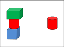
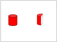
body. In figure 2, the interest has shifted to just the left half of the red cylinder and so now it is the free body on the right. The example illustrates the context sensitivity of the term "free body". A cylinder can be part of a free body, it can be a free body by itself, and, as it is composed of parts, any of those parts may be a free body in itself. Figure 1 and 2 are not yet free body diagrams. In a completed free body diagram, the free body would be shown with forces acting on it.
246:: modeling the ropes and person allows calculation of overall forces (body weight, neglecting rope weight, breezes, buoyancy, electrostatics, relativity, rotation of the earth, etc.). Then remove the person and show only one rope; you get force direction. Then only looking at the person the forces on the hand can be calculated. Now only look at the arm to calculate the forces and moments at the shoulders, and so on until the component you need to analyze can be calculated.
139:
31:
131:
676:
552:
347:
Often a provisional free body is drawn before everything is known. The purpose of the diagram is to help to determine magnitude, direction, and point of application of external loads. When a force is originally drawn, its length may not indicate the magnitude. Its line may not correspond to the exact
155:
Free body diagrams are used to visualize forces and moments applied to a body and to calculate reactions in mechanics problems. These diagrams are frequently used both to determine the loading of individual structural components and to calculate internal forces within a structure. They are used by
238:
Free body diagrams may not represent an entire physical body. Portions of a body can be selected for analysis. This technique allows calculation of internal forces, making them appear external, allowing analysis. This can be used multiple times to calculate internal forces at different locations
146:
Figure 1 shows, on the left, green, red, and blue widgets stacked on top of each other, and for some reason the red cylinder happens to be the body of interest. (It may be necessary to calculate the stress to which it is subjected, for example.) On the right, the red cylinder has become the free
126:
is said to be "free" when it is singled out from other bodies for the purposes of dynamic or static analysis. The object does not have to be "free" in the sense of being unforced, and it may or may not be in a state of equilibrium; rather, it is not fixed in place and is thus "free" to move in
770:
is a pictorial device used in analyzing mechanics problems when there is determined to be a net force and/or moment acting on a body. They are related to and often used with free body diagrams, but depict only the net force and moment rather than all of the forces being considered.
261:. This model may be used when any rotational effects are zero or have no interest even though the body itself may be extended. The body may be represented by a small symbolic blob and the diagram reduces to a set of concurrent arrows. A force on a particle is a
534:
In an analysis, a free body diagram is used by summing all forces and moments (often accomplished along or about each of the axes). When the sum of all forces and moments is zero, the body is at rest or moving and/or rotating at a constant velocity, by
661:
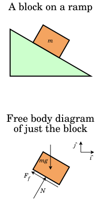
The normal force has been shown to act at the midpoint of the base, but if the block is in static equilibrium its true location is directly below the centre of mass, where the weight acts because that is necessary to compensate for the moment of the
234:
In statics all forces and moments must balance to zero; the physical interpretation is that if they do not, the body is accelerating and the principles of statics do not apply. In dynamics the resultant forces and moments can be non-zero.
774:
Kinetic diagrams are not required to solve dynamics problems; their use in teaching dynamics is argued against by some in favor of other methods that they view as simpler. They appear in some dynamics texts but are absent in others.
577:
Determining the sum of the forces and moments is straightforward if they are aligned with coordinate axes, but it is more complex if some are not. It is convenient to use the components of the forces, in which case the symbols
351:
External forces known to have negligible effect on the analysis may be omitted after careful consideration (e.g. buoyancy forces of the air in the analysis of a chair, or atmospheric pressure on the analysis of a frying pan).
710:
by attaching the beginning of one force vector to the end of another in an arbitrary order. Then the vector value of the resultant force would be determined by the missing edge of the polygon. In the diagram, the forces
665:
Unlike the weight and normal force, which are expected to act at the tip of the arrow, the friction force is a sliding vector and thus the point of application is not relevant, and the friction acts along the whole
589:
Forces and moments that are at an angle to a coordinate axis can be rewritten as two vectors that are equivalent to the original (or three, for three dimensional problems)—each vector directed along one of the axes
78:
in a given condition. It depicts a body or connected bodies with all the applied forces and moments, and reactions, which act on the body(ies). The body may consist of multiple internal members (such as a
271:. Stresses and strains are of no interest but rotational effects are. A force arrow should lie along the line of force, but where along the line is irrelevant. A force on an extended rigid body is a
398:
is always included, and chosen for convenience. Judicious selection of a coordinate system can make defining the vectors simpler when writing the equations of motion or statics. The
388:
308:
The body: This is usually a schematic depending on the body—particle/extended, rigid/non-rigid—and on what questions are to be answered. Thus if
830:
929:
219:
The number of forces and moments shown depends upon the specific problem and the assumptions made. Common assumptions are neglecting
1075:
472:(The body is not free from constraints; the constraints have just been replaced by the forces and moments exerted on the body.)
323:
The external forces: These are indicated by labelled arrows. In a fully solved problem, a force arrow is capable of indicating
205:
Moments are shown as curves with an arrow head or a vector with two arrow heads pointing in the direction they act on the body
87:). A series of free bodies and other diagrams may be necessary to solve complex problems. Sometimes in order to calculate the
1157:
380:
834:
540:
536:
508:. This should not be confused with the equal and opposite forces that are necessary to hold a body in equilibrium.)
489:
1063:
805:
838:
293:
use a diagram to explain where non specific defence are found and whether they are chemical or just barriers
991:
The Role Of The
Kinetic Diagram In The Teaching Of Introductory Rigid Body Dynamics Past, Present, And Future
1112:
728:
696:
333:
317:
161:
810:
243:
754:
702:
To graphically determine the resultant force of multiple forces, the acting forces can be arranged as
954:
789:
763:
539:. If the sum is not zero, then the body is accelerating in a direction or about an axis according to
320:
of a motorcycle cannot be found from a single point, and a sketch with finite dimensions is required.
173:
1005:
739:
yields the vertex b, etc.). The remaining edge of the polygon O-e represents the resultant force R.
650:
The force vectors show the direction and point of application and are labelled with their magnitude.
616:
All external supports and structures have been replaced by the forces they generate. These include:
285:
of a force becomes crucial and has to be indicated on the diagram. A force on a non-rigid body is a
784:
177:
138:
116:
1147:
970:
622:: the product of the mass of the block and the constant of gravitation acceleration: its weight.
289:
vector. Some use the tail of the arrow to indicate the point of application. Others use the tip.
1152:
1071:
925:
894:
795:
748:
732:
395:
372:
341:
a reaction, as opposed to an applied force, if a hash is present through the stem of the arrow
165:
316:
is in consideration, an indication of size and shape of the body is needed. For example, the
962:
384:
84:
67:
703:
692:
92:
88:
71:
958:
403:
368:
327:
220:
123:
1141:
1123:
974:
966:
520:
is being analyzed, the forces between the individual truss members are not included.)
168:, a free body diagram is an important step in understanding certain topics, such as
1030:
890:
364:
157:
130:
30:
612:
A simple free-body diagram, shown above, of a block on a ramp, illustrates this.
675:
551:
360:
212:
47:
1122:. Block Research Group (BRG) at the Institute of Technology in Architecture at
228:
202:
Forces shown as straight arrows pointing in the direction they act on the body
192:. The symbols used in a free body diagram depends upon how a body is modeled.
653:
It contains a coordinate system that can be used when describing the vectors.
488:
by a body is likely to be confusing since all the forces will cancel out. By
304:
An FBD represents the body of interest and the external forces acting on it.
17:
356:
309:
224:
800:
707:
414:
component. The force of gravity would then have components in both the
189:
169:
43:
719:
are applied to the point O. The polygon is constructed starting with P
1034:
376:
313:
134:
Figure 1: The red cylinder is the "free" body, the body of interest.
753:
550:
517:
406:
problem, for example. In that case the friction force only has an
137:
129:
80:
63:
29:
142:
Figure 2: Now the left half of the cylinder is the "free" body.
989:
586:
are used instead of ΣF (the variable M is used for moments).
27:
Diagram showing applied forces and moments on a physical body
62:) is a graphical illustration used to visualize the applied
348:
line of action. Even its orientation may not be correct.
211:
By convention, reactions to applied forces are shown with
924:(11th ed.). Pearson Prentice Hall. pp. 83–86.
945:
Puri, Avinash (1996). "The Art of Free-body
Diagrams".
857:
855:
199:
A simplified version of the body (often a dot or a box)
402:
direction may be chosen to point down the ramp in an
188:
A free body diagram is not a scaled drawing, it is a
1098:
The line of action is important where moment matters
758:
Free body and kinetic diagrams of an inclined block
91:graphically the applied forces are arranged as the
1113:"Form Diagram - Force Diagram - Free Body Diagram"
450:is the angle between the ramp and the horizontal.
127:response to forces and torques it may experience.
792:– applications of force diagram in social science
657:Some care is needed in interpreting the diagram.
355:External forces acting on an object may include
691:In the case of two applied forces, their sum (
484:(A diagram showing the forces exerted both on
1062:Rennie, Richard; Law, Jonathan, eds. (2019).
922:Engineering Mechanics: Statics & Dynamics
8:
410:component, and the normal force only has a
902:. Oxford University Press. pp. 79–105
1070:(8th ed.). Oxford University Press.
861:
674:
559:) redefined into components along axes (
208:One or more reference coordinate systems
1091:
822:
874:Ellse, Mark; Honeywell, Chris (1997).
504:exerts an equal and opposite force on
242:For example, a gymnast performing the
104:
831:"Force Diagrams (Free-body Diagrams)"
735:a). The process is repeated (adding P
608:Example: A block on an inclined plane
379:due to pushing or pulling. When in a
254:A body may be modeled in three ways:
7:
1036:Introduction to Statics and Dynamics
896:Introduction to Statics and Dynamics
695:) can be found graphically using a
83:), or be a compact body (such as a
156:most engineering disciplines from
34:Block on a ramp and corresponding
25:
988:Kraige, L. Glenn (16 June 2002),
525:Velocity or acceleration vectors.
679:A force polygon for the forces P
466:Bodies other than the free body.
383:(see coordinate system, below),
195:Free body diagrams consist of:
215:through the stem of the vector
1:
994:, pp. 7.1182.1–7.1182.11
547:Forces not aligned to an axis
381:non-inertial reference frame
835:Western Kentucky University
516:(For example, if an entire
458:A free body diagram should
1174:
967:10.1088/0031-9120/31/3/015
746:
239:within a physical body.
114:
1039:. Oxford University Press
876:Mechanics and Electricity
806:Shear and moment diagrams
747:Not to be confused with
338:the point of application
115:Not to be confused with
105:§ Polygon of forces
1068:A Dictionary of Physics
920:Hibbeler, R.C. (2007).
729:parallelogram of forces
697:parallelogram of forces
496:exerts a force on body
389:centrifugal pseudoforce
166:educational environment
759:
688:
574:
326:the direction and the
162:Structural Engineering
143:
135:
39:
1006:"Stress and Dynamics"
862:Rennie & Law 2019
811:Strength of materials
757:
678:
554:
141:
133:
33:
790:Force field analysis
283:point of application
1158:Structural analysis
1064:"polygon of forces"
959:1996PhyEd..31..155P
785:Classical mechanics
541:Newton's second law
178:classical mechanics
176:and other forms of
117:Freely falling body
72:resulting reactions
760:
689:
687:applied to point O
645:force of the ramp.
632:force of the ramp.
575:
537:Newton's first law
279:non-rigid extended
144:
136:
40:
947:Physics Education
931:978-0-13-221509-1
796:Kinematic diagram
749:Kinematic diagram
671:Polygon of forces
513:Internal forces.
396:coordinate system
391:are appropriate.
385:fictitious forces
250:Modeling the body
97:polygon of forces
52:free body diagram
36:free body diagram
16:(Redirected from
1165:
1134:
1132:
1130:
1117:
1099:
1096:
1081:
1049:
1048:
1046:
1044:
1026:
1020:
1019:
1017:
1015:
1010:
1002:
996:
995:
985:
979:
978:
942:
936:
935:
917:
911:
910:
908:
907:
901:
886:
880:
879:
871:
865:
859:
850:
849:
847:
846:
837:. Archived from
827:
490:Newton's 3rd law
312:of the body and
300:What is included
58:; also called a
21:
1173:
1172:
1168:
1167:
1166:
1164:
1163:
1162:
1138:
1137:
1128:
1126:
1115:
1111:
1108:
1103:
1102:
1097:
1093:
1088:
1078:
1061:
1058:
1053:
1052:
1042:
1040:
1028:
1027:
1023:
1013:
1011:
1008:
1004:
1003:
999:
987:
986:
982:
944:
943:
939:
932:
919:
918:
914:
905:
903:
899:
888:
887:
883:
873:
872:
868:
860:
853:
844:
842:
829:
828:
824:
819:
781:
768:kinetic diagram
752:
745:
743:Kinetic diagram
738:
726:
722:
718:
714:
693:resultant force
686:
682:
673:
639:
610:
602:
595:
585:
581:
571:
564:
549:
532:
481:the free body.
477:Forces exerted
456:
302:
296:
252:
186:
153:
120:
113:
89:resultant force
28:
23:
22:
15:
12:
11:
5:
1171:
1169:
1161:
1160:
1155:
1150:
1140:
1139:
1136:
1135:
1107:
1106:External links
1104:
1101:
1100:
1090:
1089:
1087:
1084:
1083:
1082:
1076:
1057:
1054:
1051:
1050:
1021:
997:
980:
937:
930:
912:
881:
866:
851:
821:
820:
818:
815:
814:
813:
808:
803:
798:
793:
787:
780:
777:
744:
741:
736:
724:
720:
716:
712:
684:
680:
672:
669:
668:
667:
663:
655:
654:
651:
648:
647:
646:
637:
633:
623:
609:
606:
600:
593:
583:
579:
569:
562:
555:Angled force (
548:
545:
531:
528:
527:
526:
523:
522:
521:
511:
510:
509:
475:
474:
473:
467:
455:
452:
404:inclined plane
345:
344:
343:
342:
339:
336:
330:
328:line of action
321:
301:
298:
291:
290:
276:
269:rigid extended
266:
251:
248:
221:air resistance
217:
216:
209:
206:
203:
200:
185:
182:
152:
149:
112:
109:
26:
24:
14:
13:
10:
9:
6:
4:
3:
2:
1170:
1159:
1156:
1154:
1151:
1149:
1146:
1145:
1143:
1125:
1121:
1114:
1110:
1109:
1105:
1095:
1092:
1085:
1079:
1077:9780198821472
1073:
1069:
1065:
1060:
1059:
1055:
1038:
1037:
1032:
1031:Pratap, Rudra
1029:Ruina, Andy;
1025:
1022:
1007:
1001:
998:
993:
992:
984:
981:
976:
972:
968:
964:
960:
956:
952:
948:
941:
938:
933:
927:
923:
916:
913:
898:
897:
892:
891:Pratap, Rudra
889:Ruina, Andy;
885:
882:
877:
870:
867:
863:
858:
856:
852:
841:on 2011-03-17
840:
836:
832:
826:
823:
816:
812:
809:
807:
804:
802:
799:
797:
794:
791:
788:
786:
783:
782:
778:
776:
772:
769:
765:
756:
750:
742:
740:
734:
730:
709:
705:
700:
698:
694:
677:
670:
664:
660:
659:
658:
652:
649:
644:
640:
634:
631:
627:
624:
621:
618:
617:
615:
614:
613:
607:
605:
603:
596:
587:
572:
565:
558:
553:
546:
544:
542:
538:
529:
524:
519:
515:
514:
512:
507:
503:
499:
495:
491:
487:
483:
482:
480:
476:
471:
470:
469:Constraints.
468:
465:
464:
463:
461:
453:
451:
449:
445:
441:
437:
433:
429:
425:
421:
417:
413:
409:
405:
401:
397:
394:At least one
392:
390:
386:
382:
378:
374:
370:
366:
362:
358:
353:
349:
340:
337:
335:
331:
329:
325:
324:
322:
319:
315:
311:
307:
306:
305:
299:
297:
294:
288:
284:
280:
277:
274:
270:
267:
264:
260:
257:
256:
255:
249:
247:
245:
240:
236:
232:
230:
227:and assuming
226:
222:
214:
210:
207:
204:
201:
198:
197:
196:
193:
191:
183:
181:
179:
175:
171:
167:
163:
159:
150:
148:
140:
132:
128:
125:
118:
110:
108:
106:
102:
101:force polygon
98:
94:
90:
86:
82:
77:
73:
69:
65:
61:
60:force diagram
57:
53:
49:
45:
38:of the block.
37:
32:
19:
18:Force diagram
1127:. Retrieved
1119:
1094:
1067:
1043:September 4,
1041:. Retrieved
1035:
1024:
1012:. Retrieved
1000:
990:
983:
950:
946:
940:
921:
915:
904:. Retrieved
895:
884:
875:
869:
843:. Retrieved
839:the original
825:
773:
767:
761:
701:
690:
656:
642:
635:
629:
625:
619:
611:
598:
591:
588:
576:
567:
560:
556:
533:
505:
501:
497:
493:
485:
478:
459:
457:
447:
443:
439:
435:
431:
427:
423:
422:directions:
419:
415:
411:
407:
399:
393:
365:normal force
354:
350:
346:
303:
295:
292:
286:
282:
278:
272:
268:
262:
258:
253:
241:
237:
233:
218:
194:
187:
158:Biomechanics
154:
145:
121:
100:
96:
75:
59:
55:
51:
41:
35:
1120:eQUILIBRIUM
377:human force
48:engineering
1142:Categories
1129:31 January
1124:ETH Zürich
953:(3): 155.
906:2006-08-04
845:2011-03-17
817:References
727:using the
454:Exclusions
387:, such as
318:brake dive
259:a particle
244:iron cross
229:rigid body
213:hash marks
1148:Mechanics
1014:August 5,
975:250802652
662:friction.
442:) in the
430:) in the
334:magnitude
231:action.
164:. In the
111:Free body
76:free body
1153:Diagrams
1033:(2002).
893:(2010).
779:See also
764:dynamics
643:friction
530:Analysis
492:if body
446:, where
357:friction
310:rotation
225:friction
184:Features
174:dynamics
1056:Sources
955:Bibcode
801:Physics
708:polygon
597:) and (
566:) and (
375:, or a
373:tension
361:gravity
275:vector.
273:sliding
265:vector.
190:diagram
170:statics
151:Purpose
68:moments
44:physics
1074:
973:
928:
733:vertex
641:: the
630:normal
628:: the
582:and ΣF
462:show:
314:torque
281:. The
70:, and
64:forces
1116:(PDF)
1086:Notes
1009:(PDF)
971:S2CID
900:(PDF)
723:and P
706:of a
704:edges
666:base.
518:truss
500:then
287:bound
263:bound
103:(see
95:of a
93:edges
81:truss
74:on a
1131:2024
1072:ISBN
1045:2019
1016:2015
926:ISBN
715:to P
683:to P
438:cos(
434:and
426:sin(
418:and
369:drag
332:the
223:and
124:body
85:beam
50:, a
46:and
963:doi
762:In
604:).
486:and
460:not
160:to
107:).
99:or
56:FBD
42:In
1144::
1118:.
1066:.
969:.
961:.
951:31
949:.
854:^
833:.
766:a
699:.
620:mg
578:ΣF
543:.
479:by
436:mg
424:mg
371:,
367:,
363:,
359:,
180:.
172:,
122:A
66:,
1133:.
1080:.
1047:.
1018:.
977:.
965::
957::
934:.
909:.
878:.
864:.
848:.
751:.
737:3
731:(
725:2
721:1
717:6
713:1
711:P
685:6
681:1
638:f
636:F
626:N
601:y
599:F
594:x
592:F
590:(
584:y
580:x
573:)
570:y
568:F
563:x
561:F
557:F
506:A
502:B
498:B
494:A
448:θ
444:y
440:θ
432:x
428:θ
420:y
416:x
412:y
408:x
400:x
119:.
54:(
20:)
Text is available under the Creative Commons Attribution-ShareAlike License. Additional terms may apply.