116:
17:
209:
200:
260:
388:
the unaffected cables take over its load and continue to provide service. Primary feeder outages, as well as limiters and network protectors cleared because of previous faults, cause changes in load flow that are not readily detected, so their statuses may require a periodic inspection. The inherent system redundancy generally prevents any customer from experiencing outage.
371:
315:
288:
387:
on both ends, special fuses providing very fast short-circuit protection. Cable limiters do not have an ampere rating, and cannot be used to provide overload protection; their sole purpose is to isolate the fault. Under high short-circuit conditions, limiters blow and cut off the faulted cable, while
378:
A grid networks consist of an interconnected grid of circuits, energized from several primary feeders through distribution transformers at multiple locations. Grid networks are typically featured in downtowns of large cities, with connecting cables laid out in underground conduits along the streets.
284:, or their mixture; in an overhead network, service drops are drawn from pole tops to roof connections. In a cable network, all necessary connections and protection devices are typically placed in pad-mounted cabinets or, occasionally, manholes (buried T-joint connections are prone to failures).
328:
Spot networks are used when increased reliability of supply is required for important customers. The low-voltage network is supplied from two or more distribution transformers at a single site, each fed from a different MV feeder (which may originate from the same or different substations). The
352:
Spot systems are commonly applied in high load-density areas such as business districts, large hospitals, small industry and important facilities such as water supply systems. In normal operation, the energy supply is provided by both primary feeders in parallel. In case of an outage of either
267:
Radial operation is the most widespread and most economic design of both MV and LV networks. It provides a sufficiently high degree of reliability and service continuity for most customers. In
American (120 V) systems, the customers are commonly supplied directly from the distribution
225:
ANSI standard C84.1 recommends a +5%, −2.5% tolerance for the voltage range at a service point. North
American LV networks feature much shorter secondary connections, up to 250 feet (80 m), while in European design they can reach up to 1 mile (1,600 m). North American distribution
150:
level, typically 5–35 kV. Feeders range in length from a few kilometers to several tens of kilometers. As they must supply all customers in the designated distribution area, they often curve and branch along the assigned corridors. A substation typically supplies 3–30 feeders.
226:
transformers must be therefore placed much closer to consumers, and are smaller (25–50 kVA), while
European ones can cover larger areas and thus have higher ratings (300–1000 kVA); only the remote rural areas in European design are served by single-phase transformers.
169:). Typically, a rural primary feeder supplies up to 50 distribution transformers, spread over a wide region, but the figure significantly varies depending on configuration. They are sited on pole tops, cellars or designated small plots. From these transformers,
361:
is located at the paralleling bus, or a total loss of primary supply occurs, the customer will remain out of service. Faults on the low-voltage network are handled by fuses or local circuit breakers, resulting in loss of service only for the affected loads.
133:
systems are designed to serve their customers with reliable and high-quality power. The most common distribution system consists of simple radial circuits (feeders) that can be overhead, underground, or a combination. From the
382:
As with spot networks, network protectors are used to protect against primary feeder faults, and prevent fault current to propagate from the grid to the primary feeder. Individual cable sections may be protected by
229:
As the low-voltage distribute the electric power to the widest class of end users, another main design concern is safety of consumers who use the electric appliances and their protection against electric shocks. An
357:
device at the corresponding spot transformer secondary automatically opens; the remaining transformers continue to provide supply through their respective primary feeders. Only in cases when the
242:, must ultimately ensure that a person must not come into touch with a metallic object whose potential relative to the person's potential (which is, in turn, equal to the ground potential unless
349:. In some cases, fast-acting secondary bus tie breakers may be applied between bus sections to isolate faults in the secondary switchgear and limit loss of service.
83:
lines from the transformer to the customer premises. Low-voltage radial feeders supply multiple customers. For increased reliability, so-called
724:
703:
661:
609:
298:
in radial networks is simple to design and implement, since short-circuit currents have only one possible path that needs to be interrupted.
743:
20:
A pole-mounted three-phase distribution transformer. Low-voltage feeders distributing power to households are placed below the transformer
682:
222:
rating. In Europe and most of the world 220–240 V is the dominant choice, while in North
America 120 V is the standard.
291:
Low-voltage side switching cabinet of a
European MV/LV substation. Four LV cable feeders equipped with circuit breakers featured.
272:
lines, in star-like topology. In 240 V systems, the customers are served by several low-voltage feeders, realized by
115:
68:
621:"Secondary Network Distribution Systems Background and Issues Related to the Interconnection of Distributed Resources"
130:
33:
582:
402:
154:
37:
323:
295:
239:
135:
79:) and required reliability dictate topology and configuration of the network. The simplest form are radial
16:
634:
Confidence
Interval Estimation for Distribution Systems Power Consumption by using the Bootstrap Method
379:
Numerous cables allow for multiple current paths from every transformer to every load within the grid.
277:
100:
243:
147:
273:
96:
56:
208:
199:
720:
699:
678:
657:
651:
605:
354:
299:
235:
178:
41:
672:
599:
638:
397:
303:
231:
124:
92:
302:
are most commonly used for both short-circuit and overload protection, while low-voltage
218:
Most of differences in the layout and design of low-voltage networks are dictated by the
91:
provide supply of customers from multiple distribution transformers and supply paths.
737:
384:
358:
219:
177:
network branches off to the customer connections at customer premises, equipped with
166:
49:
329:
transformers are connected together with a bus or a cable on secondary side, termed
269:
80:
76:
714:
693:
192:
Typical layouts of
European (left) and North American (right) distribution system
281:
162:
120:
104:
72:
45:
637:(Doctoral dissertation). Virginia Polytechnic Institute and State University.
620:
259:
619:
Behnke, Michael; Soudi, Farajollah; Feero, William; Dawson, Douglas (2005).
370:
314:
246:
are used) exceeds a "safe" threshold, typically set at about 50 V.
642:
287:
632:
583:"ANSI C84.1 Electric Power Systems And Equipment - Voltage Ranges"
369:
313:
286:
258:
114:
64:
60:
15:
341:) to other network units, in which case such networks are termed
337:. The paralleling bus typically does not have connecting cables (
161:, placed along feeders, convert the voltage from the medium to a
653:
Design
Fundamentals for Low-Voltage Distribution and Control
138:, feeders carry the power to the end customers, forming the
119:
A house cable connection cabinet equipped with a meter, a
601:
165:
level, suitable for direct consumption by end customers (
631:
44:
of end customers. Secondary networks are operated at a
514:
512:
510:
473:
471:
446:
444:
431:
429:
695:Electric Power Distribution Equipment and Systems
234:, in combination with protective devices such as
71:). Operating voltage, required number of phases (
55:Most modern secondary networks are operated at
674:Electrical Raceways & Other Wiring Methods
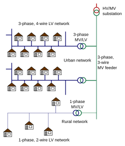
263:Typical layouts of radial low-voltage networks
8:
716:Newnes Electrical Power Engineer's Handbook
345:; when they have, they are referred to as
59:rated voltage of 100–127 or 220–240
626:. National Renewable Energy Laboratory.
413:
48:level, which is typically equal to the
306:may be used in special circumstances.
554:
477:
462:
450:
420:
7:
566:
542:
530:
518:
501:
489:
435:
374:Layout of a grid low-voltage network
318:Layout of a spot low-voltage network
63:, at the frequency of 50 or 60
36:which carries electric energy from
268:transformers via relatively short
14:
650:Kussy, Frank (8 December 1986).
604:. PennWell Books. pp. 82–.
207:
198:
1:
692:Short, Thomas Allen (2005).
69:mains electricity by country
744:Electric power distribution
713:Warne, D.F. (2 June 2005).
131:Electric power distribution
34:electric power distribution
760:
403:Split-phase electric power
321:
671:Loyd, Richard E. (2004).
155:Distribution transformers
38:distribution transformers
598:Beaty, H. Wayne (1998).
347:spot networks with reach
240:residual current devices
52:of electric appliances.
343:isolating spot networks
324:Spot network substation
296:Power-system protection
146:network, operated at a
136:distribution substation
375:
319:
292:
264:
159:secondary transformers
127:
21:
373:
317:
290:
262:
185:Design considerations
118:
19:
677:. Cengage Learning.
274:overhead power lines
107:, or their mixture.
97:overhead power lines
95:can be realized by
26:low-voltage network
376:
320:
293:
265:
179:electricity meters
128:
42:electricity meters
22:
726:978-0-08-047969-9
705:978-1-4200-3647-3
663:978-0-8247-7515-5
611:978-0-87814-731-1
355:network protector
30:secondary network
751:
730:
709:
688:
667:
646:
627:
625:
615:
594:
592:
590:
570:
564:
558:
552:
546:
540:
534:
528:
522:
516:
505:
499:
493:
487:
481:
475:
466:
460:
454:
448:
439:
433:
424:
418:
353:primary feeder,
304:circuit breakers
211:
202:
759:
758:
754:
753:
752:
750:
749:
748:
734:
733:
727:
712:
706:
691:
685:
670:
664:
649:
630:
623:
618:
612:
597:
588:
586:
581:
578:
573:
565:
561:
553:
549:
541:
537:
529:
525:
521:, pp. 6–8.
517:
508:
500:
496:
488:
484:
476:
469:
461:
457:
449:
442:
434:
427:
419:
415:
411:
398:Earthing system
394:
368:
331:paralleling bus
326:
312:
280:or underground
257:
255:Radial networks
252:
244:insulating mats
232:earthing system
216:
215:
214:
213:
212:
204:
203:
194:
193:
187:
125:circuit breaker
113:
103:or underground
93:Electric wiring
12:
11:
5:
757:
755:
747:
746:
736:
735:
732:
731:
725:
710:
704:
689:
683:
668:
662:
647:
628:
616:
610:
595:
577:
574:
572:
571:
559:
557:, p. 298.
547:
535:
523:
506:
494:
482:
467:
465:, p. 387.
455:
440:
425:
423:, p. 385.
412:
410:
407:
406:
405:
400:
393:
390:
385:cable limiters
367:
364:
322:Main article:
311:
308:
256:
253:
251:
248:
206:
205:
197:
196:
195:
191:
190:
189:
188:
186:
183:
148:medium voltage
140:medium-voltage
112:
109:
13:
10:
9:
6:
4:
3:
2:
756:
745:
742:
741:
739:
728:
722:
718:
717:
711:
707:
701:
698:. CRC Press.
697:
696:
690:
686:
684:1-4018-5183-5
680:
676:
675:
669:
665:
659:
656:. CRC Press.
655:
654:
648:
644:
640:
636:
635:
629:
622:
617:
613:
607:
603:
602:
596:
584:
580:
579:
575:
569:, p. 10.
568:
563:
560:
556:
551:
548:
544:
539:
536:
532:
527:
524:
520:
515:
513:
511:
507:
504:, p. 18.
503:
498:
495:
491:
486:
483:
480:, p. 23.
479:
474:
472:
468:
464:
459:
456:
453:, p. 84.
452:
447:
445:
441:
437:
432:
430:
426:
422:
417:
414:
408:
404:
401:
399:
396:
395:
391:
389:
386:
380:
372:
366:Grid networks
365:
363:
360:
359:short circuit
356:
350:
348:
344:
340:
336:
335:collector bus
332:
325:
316:
310:Spot networks
309:
307:
305:
301:
297:
289:
285:
283:
279:
275:
271:
261:
254:
249:
247:
245:
241:
237:
233:
227:
223:
221:
220:mains voltage
210:
201:
184:
182:
180:
176:
172:
168:
167:mains voltage
164:
160:
156:
152:
149:
145:
141:
137:
132:
126:
122:
117:
110:
108:
106:
102:
98:
94:
90:
89:grid networks
86:
85:spot networks
82:
78:
74:
70:
66:
62:
58:
53:
51:
50:mains voltage
47:
43:
39:
35:
32:is a part of
31:
27:
18:
719:. Elsevier.
715:
694:
673:
652:
633:
600:
589:21 September
587:. Retrieved
562:
550:
545:, p. 7.
538:
533:, p. 9.
526:
497:
485:
458:
438:, p. 1.
416:
381:
377:
351:
346:
342:
338:
334:
330:
327:
294:
282:power cables
270:service drop
266:
228:
224:
217:
174:
170:
158:
153:
143:
139:
129:
105:power cables
88:
84:
81:service drop
77:single-phase
54:
29:
25:
23:
643:10919/36841
171:low-voltage
163:low voltage
121:time switch
73:three-phase
46:low voltage
576:References
555:Kussy 1986
478:Warne 2005
463:Warne 2005
451:Beaty 1998
421:Warne 2005
567:NREL 2005
543:NREL 2005
531:NREL 2005
519:NREL 2005
502:Loyd 2004
490:ANSI 2011
436:NREL 2005
409:Footnotes
175:secondary
738:Category
392:See also
250:Topology
111:Overview
339:reaches
144:primary
723:
702:
681:
660:
608:
585:. 2011
278:aerial
123:and a
101:aerial
624:(PDF)
300:Fuses
236:fuses
67:(see
65:hertz
61:volts
721:ISBN
700:ISBN
679:ISBN
658:ISBN
606:ISBN
591:2017
238:and
87:and
639:hdl
333:or
173:or
157:or
142:or
75:or
40:to
28:or
740::
509:^
470:^
443:^
428:^
276:,
181:.
99:,
57:AC
24:A
729:.
708:.
687:.
666:.
645:.
641::
614:.
593:.
492:.
Text is available under the Creative Commons Attribution-ShareAlike License. Additional terms may apply.