17:
162:
82:
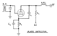
passed through a plate load impedance chosen to produce the desired amplification in conjunction with the tube characteristics. A capacitor of low impedance at the carrier frequency and high impedance at audio frequencies is provided between the tube plate and cathode, to minimize amplification of the carrier frequency and remove carrier frequency variations from the recovered modulation waveform. The allowable peak 100% modulated input signal voltage is limited to the magnitude of the bias voltage, corresponding to an unmodulated carrier peak voltage of half the bias voltage magnitude.
57:
suited to the higher radio frequency signal level than the plate detector. Diode detectors also became popular during the later 1920s because, unlike plate detector circuits, they could also provide automatic gain control voltage (A.V.C.) for the radio frequency amplifier stages of the receiver. However, the
169:
In the
Infinite-Impedance detector, the load resistance is placed in series with the cathode, rather than the plate, and the demodulated output is taken from the cathode. The circuit is operated in the region where grid current does not occur during any portion of the carrier frequency cycle, thus
56:
Plate detector circuits were most commonly used from the 1920s until the start of World War II. In 1927, the advent of screen grid tubes permitted much more radio frequency amplification before the detector stage than previously practically possible. The previously used grid leak detector was less
173:
As with the standard plate detector, the device is biased almost completely off. The positive-going 180 degrees of the carrier input signal causes a substantial increase of cathode or source current above the amount set by the bias, and the negative-going 180 degrees of the carrier cycle causes a
81:
transformer. An incoming signal will cause the plate current to increase much more during the positive 180 degrees of the carrier frequency cycle than it decreases during the negative 180 degrees. The plate current variation will include the original modulation frequencies. The plate current is
98:
Plate detector circuits usually do not produce A.V.C. voltage for the radio frequency (R.F.) stages of the receiver. In these receivers, volume control is often accomplished by providing variable cathode bias of one or more stages prior to the detector. A potentiometer is used to implement the
121:
A potentiometer (typically 500 kΩ audio taper) where the high end and center wiper are connected as above, but where the low end is connected to the control grid of audio output tube. (In this circuit, the potentiometer replaces the bias resistor for the output tube's control
89:
or cathode bias may be used for the plate detector. When cathode bias is implemented, a capacitor of low impedance at the carrier frequency and high impedance at audio frequencies bypasses the cathode resistor. Cathode bias reduces the amplification obtainable.
113:
To set a limit on the ability of the volume control to reduce the bias on the stages that it controls, the potentiometer is often equipped with a mechanical rotation limit facility that prevents the resistance from being reduced below a specific amount.
198:
to follow the modulation envelope. Negative feedback takes place at the recovered modulation frequencies, reducing distortion. The infinite impedance detector can demodulate higher modulation percentages with less distortion than the plate detector.
109:
The other end of the potentiometer is connected to the cathode of at least one R.F. amplifier (in T.R.F. receivers) or the cathode of the converter and/or the I.F. amplifier (in superheterodyne receivers).
134:
Because the volume control in non-A.V.C. receivers adjusts R.F. signal levels rather than A.F. signal levels, the volume control must be manipulated while tuning the radio in order to find weak signals.
40:
circuit in which an amplifying tube having a control grid is operated in a non-linear region of its grid voltage versus plate current transfer characteristic, usually near plate current cutoff, to
65:
costs that were as much as twice the cost of the tubes commonly used as plate detectors. This made plate detector circuits more practical for low-priced radios sold during the depths of the
48:, which utilizes the non-linearity of the grid voltage versus grid current characteristic for demodulation. It also differs from the diode detector, which is a two-terminal device.
128:
A linear taper potentiometer connected to the antenna (high end), ground (low end) and the antenna transformer primary or first tuned circuit (center wiper).
16:
77:
Negative bias is applied to the grid to bring the plate current almost to cutoff. The grid is connected directly to the secondary of a radio frequency or
633:
672:
170:
the name "Infinite
Impedance Detector". An example schematic diagram of an implementation using a field effect transistor is shown.
161:
592:
657:
125:
A linear taper potentiometer that adjusts the screen grid voltages of the R.F. amplifiers (if they are tetrodes or pentodes);
99:
variable cathode bias. The most common connection of the potentiometer (typically 4 kΩ to 15 kΩ linear taper) is as follows:
734:
577:
20:
Plate detector circuit with cathode bias. Cathode bias RC time constant three times period of lowest carrier frequency. C
194:
time constant is much shorter than the period of the highest modulating frequency, permitting the voltage across C
755:
218:
values of 100 to 500 picofarads being typical. The low pass filter in the V+ power supply line, C4 and the RFC (
750:
226:
coupling through the power supply to other circuitry and does not contribute to the function of the detector.
146:
01A, 1H4G, 6C6, 6J7, 6SJ7, 12F5, 12J5, 12J7, 12SF5, 12SJ7, 24, 24A, 27, 30, 36, 37, 56, 57, 76, 77, 201A, 301A
288:
258:
78:
760:
538:
219:
58:
45:
724:
714:
66:
223:
106:
The wiper is connected to ground (in A.C. receivers) or B minus (in A.C./D.C. receivers);
744:
728:
460:
718:
41:
607:
H. A. Robinson, "The
Operating Characteristics of Vacuum Tube Detectors", Part 1.
61:
and dual-diode/pentode tubes commonly used for detection/A.V.C. circuits had bulk
214:
is chosen to be several times the period of the lowest carrier frequency, with C
37:
206:
values of 50,000 to 150,000 ohms are typical for tubes. The time constant of C
496:
103:
One end of the potentiometer is connected to the antenna coupling component;
62:
717:
Two typical superheterodyne radios with a triode plate detector. Sold by
174:
very little decrease of cathode current below the level set by the bias. C
186:, and the circuit acts as a peak detector at the carrier frequency. The C
737:
Circuit description of a typical JFET-based infinite impedance detector.
86:
160:
15:
178:
is charged to a dc voltage determined by the carrier amplitude. C
727:
A typical T.R.F. radio with a pentode plate detector. Sold by
118:
Other volume control circuits in non-A.V.C. receivers include:
689:
480:
470:
735:
JFET-based infinite impedance detector for AM-demodulation
44:
amplitude modulated carrier signal. This differs from the
165:
Infinite-Impedance
Detector (Modern JFET Implementation)
546:(from crystal sets to mass-produced transistor radios)
624:, Chandler, AZ: Sonoran Publishing LLC, 2007, p. 336
638:, London: The Amalgamated Press LTD., 1933, p. 115
597:, 2nd ed. New York: McGraw-Hill, 1937, pp. 433-446
725:Schematic of "Silvertone" models 6114 and 6115.
687:B. Goodman, "The Infinite Impedance Detector",
662:, no. 905, vol. XL, no. 1, Jan. 1st 1937, p. 6
152:Comparison with Alternative Envelope Detectors
715:Schematics of Packard Bell models 35A and 65.
582:, New York: John Wiley and Sons, 1943, p. 105
8:
622:Radiola: the Golden Age of RCA, 1919 - 1929
222:) shown in the diagram, minimizes unwanted
233:
561:
34:anode bend detector, grid bias detector
658:W. N. Weeden, "New Detector Circuit",
139:Tubes commonly used as plate detectors
677:, New York: McGraw-Hill, 1947, p. 710
573:
571:
569:
567:
565:
407:(unless bias is applied to overcome V
7:
611:, vol. XIV, no. 8, p. 27, Aug. 1930
14:
693:, vol. XXIII, p. 21, Oct. 1939
1:
675:Electronic Circuits and Tubes
580:The Technique of Radio Design
419:(depends on op-amp employed)
182:can only be discharged via R
243:Infinite-impedance detector
157:Infinite-Impedance Detector
24:is typically around 250 pF.
777:
636:The Manual of Modern Radio
673:Cruft Electronics Staff,
595:Communication Engineering
527:
505:
487:(with appropriate diodes)
452:Maximum usable frequency
451:
425:
359:Loading of tuned circuit
332:
316:(offset voltage too high)
298:(offset voltage too high)
286:
256:
236:
531:Old short-wave receivers
528:Most commonly found in:
94:Controlling volume level
534:High fidelity AM tuners
539:regenerative receivers
230:Summary of Differences
166:
79:intermediate frequency
25:
164:
19:
648:W.L. Everitt, p. 434
252:Precision Rectifier
721:in the early 1930s.
506:Circuit Complexity
333:Typical Distortion
634:J. Scott-Taggart,
543:Most AM receivers
386:Quiescent current
246:Grid-leak detector
167:
46:grid leak detector
28:In electronics, a
26:
554:
553:
547:
501:
488:
465:
421:
412:
318:
309:
300:
59:dual-diode/triode
768:
756:Radio technology
703:
702:B. Goodman, 1939
700:
694:
685:
679:
670:
664:
655:
649:
646:
640:
631:
625:
618:
612:
605:
599:
590:
584:
575:
545:
493:
485:
456:
417:
406:
314:
307:(positive-going)
305:
296:
234:
67:Great Depression
776:
775:
771:
770:
769:
767:
766:
765:
751:Analog circuits
741:
740:
711:
706:
701:
697:
686:
682:
671:
667:
656:
652:
647:
643:
632:
628:
619:
615:
606:
602:
593:W. L. Everitt,
591:
587:
576:
563:
559:
550:Test equipment
544:
492:
486:
468:can be used at
457:
444:
416:
410:
405:
313:
304:
295:
259:Directly-Heated
232:
217:
213:
209:
205:
197:
193:
189:
185:
181:
177:
159:
154:
141:
96:
75:
54:
23:
12:
11:
5:
774:
772:
764:
763:
758:
753:
743:
742:
739:
738:
732:
722:
710:
709:External links
707:
705:
704:
695:
680:
665:
660:Wireless World
650:
641:
626:
620:E. P. Wenaas,
613:
600:
585:
560:
558:
555:
552:
551:
548:
541:
535:
532:
529:
525:
524:
521:
516:
513:
510:
507:
503:
502:
489:
477:
474:
466:
453:
449:
448:
441:
438:
433:
430:
427:
423:
422:
413:
408:
400:
397:
392:
387:
383:
382:
376:
373:
370:
365:
360:
356:
355:
350:
347:
344:
339:
334:
330:
329:
324:
319:
310:
301:
292:
284:
283:
280:
275:
270:
267:
262:
254:
253:
250:
249:Diode detector
247:
244:
241:
240:Plate detector
238:
231:
228:
215:
211:
207:
203:
195:
191:
187:
183:
179:
175:
158:
155:
153:
150:
149:
148:
140:
137:
132:
131:
130:
129:
126:
123:
111:
110:
107:
104:
95:
92:
74:
71:
53:
50:
30:plate detector
21:
13:
10:
9:
6:
4:
3:
2:
773:
762:
759:
757:
754:
752:
749:
748:
746:
736:
733:
730:
729:Sears Roebuck
726:
723:
720:
716:
713:
712:
708:
699:
696:
692:
691:
684:
681:
678:
676:
669:
666:
663:
661:
654:
651:
645:
642:
639:
637:
630:
627:
623:
617:
614:
610:
604:
601:
598:
596:
589:
586:
583:
581:
578:E.E. Zepler,
574:
572:
570:
568:
566:
562:
556:
549:
542:
540:
536:
533:
530:
526:
522:
520:
517:
514:
511:
508:
504:
500:
498:
490:
484:
482:
478:
475:
473:
472:
467:
464:
462:
461:Miller effect
454:
450:
447:
442:
439:
437:
434:
431:
428:
426:Voltage Gain
424:
420:
414:
404:
401:
398:
396:
393:
391:
388:
385:
384:
381:
377:
374:
371:
369:
366:
364:
361:
358:
357:
354:
351:
348:
345:
343:
340:
338:
335:
331:
328:
325:
323:
320:
317:
311:
308:
302:
299:
293:
290:
287:Suitable for
285:
281:
279:
276:
274:
271:
268:
266:
263:
260:
257:Suitable for
255:
251:
248:
245:
242:
239:
235:
229:
227:
225:
221:
200:
171:
163:
156:
151:
147:
143:
142:
138:
136:
127:
124:
120:
119:
117:
116:
115:
108:
105:
102:
101:
100:
93:
91:
88:
85:Either fixed
83:
80:
72:
70:
68:
64:
60:
51:
49:
47:
43:
39:
35:
31:
18:
761:Vacuum tubes
719:Packard Bell
698:
688:
683:
674:
668:
659:
653:
644:
635:
629:
621:
616:
608:
603:
594:
588:
579:
537:Single-tube
518:
494:
479:
469:
463:limitations)
458:
445:
435:
418:
402:
394:
389:
379:
367:
362:
352:
341:
336:
326:
321:
315:
306:
297:
277:
272:
264:
201:
172:
168:
145:
133:
112:
97:
84:
76:
55:
33:
29:
27:
403:Low or None
291:production
38:vacuum tube
745:Categories
557:References
483:and beyond
42:demodulate
497:slew rate
446:(usually)
380:(Usually)
282:Unlikely
237:Detector:
73:Operation
63:wholesale
731:in 1939.
523:Highest
499:limited)
395:Very low
390:Very low
342:Very low
220:RF Choke
378:Medium
52:History
36:) is a
519:Lowest
443:Unity
429:Medium
372:Medium
349:Medium
346:Medium
261:tubes
210:with R
122:grid);
455:High
432:Unity
415:High
411:drop)
491:Low
476:High
436:High
399:High
375:High
87:bias
690:QST
609:QST
515:Low
512:Low
509:Low
481:UHF
471:VHF
440:Low
368:Low
363:Low
353:Low
337:Low
327:Yes
322:Yes
312:No
303:No
294:No
289:AGC
278:Yes
273:Yes
265:Yes
747::
564:^
269:No
224:RF
69:.
495:(
459:(
409:f
216:2
212:1
208:2
204:1
202:R
196:2
192:1
190:R
188:2
184:1
180:2
176:2
144:'
32:(
22:L
Text is available under the Creative Commons Attribution-ShareAlike License. Additional terms may apply.