644:
632:
620:
688:: It is an improved version of a counting ADC. The circuit consists of an up-down counter with the comparator controlling the direction of the count. The analog output of the DAC is compared with the analog input. If the input is greater than the DAC output signal, the output of the comparator goes high and the counter is caused to count up. The tracking ADC has the advantage of being simple. The disadvantage, however, is the time needed to stabilize as a new conversion value is directly proportional to the rate at which the analog signal changes.
36:
243:
554:
101:
833:(e.g. 1.1, 2.12, 4.05, 8.01, etc.) – a successive-approximation approach might not output the ideal value because the binary search algorithm incorrectly removes what it believes to be half of the values the unknown input cannot be. Depending on the difference between actual and ideal performance, the maximal error can easily exceed several LSBs, especially as the error between the actual and ideal
698:
717:
657:
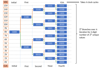
Successive steps involve taking the identified region from before and further dividing the region into two and continuing identification. This occurs until all possible choices of digital representations are exhausted, leaving behind an identified region that corresponds to only one of the digital representations.
713:. The charge-scaling DAC simply consists of an array of individually switched binary-weighted capacitors. The amount of charge upon each capacitor in the array is used to perform the aforementioned binary search in conjunction with a comparator internal to the DAC and the successive-approximation register.
656:
The successive approximation ADC can be alternatively explained by first uniformly assigning each digital output to corresponding ranges as shown. It can be seen that the algorithm essentially divides the voltage range into two regions and checks which of the two regions the input voltage belongs to.
592:
The working of a 4-bit successive approximation ADC is illustrated below. The MSB is initially set to 1 whereas the remaining digits are set to zero. If the input voltage is lower than the value stored in the register, on the next clock cycle, the register changes its value to that illustrated in the
585:
When the analog input is being compared to the internal DAC output, it effectively is being compared to each of these binary weights, starting with the 2.5 V and either keeping it or clearing it as a result. Then by adding the next weight to the previous result, comparing again, and repeating
577:
The ten steps to converting an analog input to 10 bit digital, using successive approximation, are shown here for all voltages from 5 V to 0 V in 0.1 V iterations. Since the reference voltage is 5 V, when the input voltage is also 5 V, all bits are set. As the voltage is
604:
In n-th clock cycle, if voltage is higher than digital equivalent voltage of the number in register, the (n+1)-th digit from the left is set to 1. If the voltage were lower than digital equivalent voltage, then n-th digit from left is set to zero and the next digit is set to 1. To perform a
820:, then the comparator outputs a digital 1 as the MSB, otherwise it outputs a digital 0 as the MSB. Each capacitor is tested in the same manner until the comparator input voltage converges to the offset voltage, or at least as close as possible given the resolution of the DAC.
581:
The binary weights assigned to each bit, starting with the MSB, are 2.5, 1.25, 0.625, 0.3125, 0.15625, 0.078125, 0.0390625, 0.01953125, 0.009765625, 0.0048828125. All of these add up to 4.9951171875, meaning binary 1111111111, or one LSB less than 5.
593:
figure by following the green line. If the input voltage is higher, then on the next clock cycle, the register changes its value to that illustrated in the figure by following the red line. The simplified structure of this type of ADC that acts on
771:, which corresponds to the full-scale range of the ADC. Due to the binary-weighting of the array, the MSB capacitor forms a 1:1 charge divider with the rest of the array. Thus, the input voltage to the comparator is now
104:
Successive-approximation ADC block diagram showing digital-to-analog converter (DAC), end of conversion indicator (EOC), successive approximation register (SAR), sample and hold circuit (S/H), input voltage
837:
becomes large for one or more bits. Since the actual input is unknown, it is therefore very important that accuracy of the analog circuit used to implement a SAR ADC be very close to the ideal
282:
until every bit in the SAR has been tested. The resulting code is the digital approximation of the sampled input voltage and is finally output by the SAR at the end of the conversion (EOC).
669:: The D to A converter can be easily turned around to provide the inverse function A to D conversion. The principle is to adjust the DAC's input code until the DAC's output comes within
65:
578:
decreased to 4.9 V, only some of the least significant bits are cleared. The MSB will remain set until the input is one half the reference voltage, 2.5 V.
625:
Setup where output values of the ADC are arranged in a grid, vertical axis corresponding to voltage. It is a 4-bit ADC that measures input voltages from 0V to 15V.
278:, then the comparator causes the SAR to reset this bit; otherwise, the bit is left as 1. Then the next bit is set to 1 and the same test is done, continuing this
734:. This step provides automatic offset cancellation (i.e. the offset voltage represents nothing but dead charge, which can't be juggled by the capacitors).
911:
880:
746:. The capacitors now have a charge equal to their respective capacitance times the input voltage minus the offset voltage upon each of them.
586:
until all the bits and their weights have been compared to the input, the result, a binary number representing the analog input, is found.
749:
The capacitors are then switched so that this charge is applied across the comparator input, creating a comparator input voltage equal to
932:
893:
87:
148:
643:
631:
927:
48:
855:
710:
196:
160:
132:
58:
52:
44:
619:
69:
937:
942:
279:
269:
into the comparator circuit for comparison with the sampled input voltage. If this analog voltage exceeds
557:
Operation of successive-approximation ADC as input voltage falls from 5 to 0 V. Iterations on the
242:
251:
850:
258:
1. This code is fed into the DAC, which then supplies the analog equivalent of this digital code
206:
A successive-approximation register subcircuit designed to supply an approximate digital code of
200:
829:
When implemented as an analog circuit – where the value of each successive bit is not perfectly
889:
876:
17:
397:
168:
136:
905:
725:
The capacitor array is completely discharged to the offset voltage of the comparator,
921:
144:
100:
255:
140:
605:
conversion, an N-bit ADC requires N such clock cycles excluding the initial state.
762:
The actual conversion process proceeds. First, the MSB capacitor is switched to
705:
One of the most common implementations of the successive-approximation ADC, the
307:
in is the normalized input voltage. The objective is to approximately digitize
697:
553:
228:
151:
levels before finally converging upon a digital output for each conversion.
906:
Understanding SAR ADCs: Their
Architecture and Comparison with Other ADCs
637:
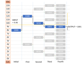
Previously established setup where an input voltage of 10.4V is provided.
199:
and outputs the result of the comparison to the successive-approximation
737:
All of the capacitors within the array are switched to the input signal
682:
LSB to the analog input which is to be converted to binary digital form.
649:
Previously established setup where an input voltage of 9.4V is provided.
601:
Initialize register with MSB set to 1 and all other values set to zero.
172:
716:
715:
696:
552:
241:
250:
The successive approximation register is initialized so that the
231:
with an analog voltage equal to the digital code output of the
29:
841:
values; otherwise, it cannot guarantee a best match search.
518:
A register to store the output of the comparator and apply
873:
CMOS Circuit Design, Layout, and
Simulation, 3rd Edition
515:
by comparing the DAC's voltage with the input voltage.
163:
circuit typically consists of four chief subcircuits:
447:
As shown in the above algorithm, a SAR ADC requires:
709:
successive-approximation ADC, uses a charge-scaling
218:
An internal reference DAC that, for comparison with
912:
Choose the right A/D converter for your application
693:Charge-redistribution successive-approximation ADC
246:Animation of a 4-bit successive-approximation ADC
426:). It follows using mathematical induction that
57:but its sources remain unclear because it lacks
597:volts range can be expressed as an algorithm:
875:; R. J. Baker; Wiley-IEEE; 1208 pages; 2010;
8:
888:; Analog Devices; Newnes; 976 pages; 2004;
186:An analog voltage comparator that compares
88:Learn how and when to remove this message
99:
612:Working of successive approximation ADC
720:3 bits simulation of a capacitive ADC
495:A comparator to perform the function
323:. The algorithm proceeds as follows:
7:
27:Type of analog-to-digital converter
825:Use with non-ideal analog circuits
25:
561:axis. Approximation value on the
135:(ADC) that converts a continuous
642:
630:
618:
34:
195:to the output of the internal
1:
171:circuit to acquire the input
159:The successive-approximation
129:successive-approximation ADC
18:Successive approximation ADC
856:Digital-to-analog converter
463:A reference voltage source
161:analog-to-digital converter
133:analog-to-digital converter
959:
933:Digital signal processing
114:) and reference voltage (
886:Data Conversion Handbook
451:An input voltage source
43:This article includes a
472:to normalize the input.
143:representation using a
72:more precise citations.
721:
702:
566:
327:Initial approximation
247:
124:
719:
707:charge-redistribution
700:
556:
475:A DAC to convert the
245:
147:through all possible
103:
285:Mathematically, let
254:(MSB) is equal to a
252:most significant bit
215:to the internal DAC.
928:Electronic circuits
796:. Subsequently, if
851:Quantization noise
722:
703:
701:Charge-scaling DAC
686:Servo tracking ADC
567:
313:to an accuracy of
248:
125:
45:list of references
881:978-0-470-88132-3
98:
97:
90:
16:(Redirected from
950:
840:
836:
832:
819:
818:
814:
805:is greater than
804:
795:
794:
793:
789:
770:
758:
745:
733:
681:
680:
679:
675:
667:Counter type ADC
646:
634:
622:
596:
548:
514:
491:
480:
471:
459:
442:
425:
418:
414:
407:
395:
384:
344:
336:
322:
321:
317:
312:
306:
300:
277:
268:
237:
226:
214:
194:
182:
139:into a discrete
122:
113:
93:
86:
82:
79:
73:
68:this article by
59:inline citations
38:
37:
30:
21:
958:
957:
953:
952:
951:
949:
948:
947:
938:Analog circuits
918:
917:
902:
869:
867:Further reading
864:
847:
838:
834:
830:
827:
816:
813:
807:
806:
803:
797:
791:
788:
782:
781:
779:
772:
769:
763:
757:
750:
744:
738:
732:
726:
695:
677:
673:
672:
670:
663:
654:
653:
652:
651:
650:
647:
639:
638:
635:
627:
626:
623:
614:
613:
594:
572:
542:
528:
519:
508:
496:
490:
482:
476:
470:
464:
458:
452:
436:
427:
420:
416:
409:
401:
398:signum function
386:
378:
364:
354:
346:
340:
334:
328:
319:
315:
314:
308:
302:
299:
292:
286:
276:
270:
266:
259:
236:
232:
227:, supplies the
225:
219:
213:
207:
193:
187:
181:
175:
169:sample-and-hold
157:
137:analog waveform
121:
115:
112:
106:
94:
83:
77:
74:
63:
49:related reading
39:
35:
28:
23:
22:
15:
12:
11:
5:
956:
954:
946:
945:
943:Approximations
940:
935:
930:
920:
919:
916:
915:
909:
901:
900:External links
898:
897:
896:
894:978-0750678414
883:
868:
865:
863:
860:
859:
858:
853:
846:
843:
826:
823:
822:
821:
811:
801:
786:
777:
767:
760:
755:
747:
742:
735:
730:
694:
691:
690:
689:
683:
662:
659:
648:
641:
640:
636:
629:
628:
624:
617:
616:
615:
611:
610:
609:
608:
607:
606:
602:
571:
568:
551:
550:
537:
523:
516:
504:
493:
486:
481:approximation
473:
468:
461:
456:
445:
444:
432:
373:
359:
350:
345:approximation
338:
332:
297:
290:
274:
264:
240:
239:
234:
223:
216:
211:
204:
191:
184:
179:
156:
153:
119:
110:
96:
95:
53:external links
42:
40:
33:
26:
24:
14:
13:
10:
9:
6:
4:
3:
2:
955:
944:
941:
939:
936:
934:
931:
929:
926:
925:
923:
913:
910:
907:
904:
903:
899:
895:
891:
887:
884:
882:
878:
874:
871:
870:
866:
861:
857:
854:
852:
849:
848:
844:
842:
824:
810:
800:
785:
776:
766:
761:
754:
748:
741:
736:
729:
724:
723:
718:
714:
712:
708:
699:
692:
687:
684:
668:
665:
664:
660:
658:
645:
633:
621:
603:
600:
599:
598:
591:
587:
583:
579:
576:
569:
564:
560:
555:
546:
540:
536:
532:
526:
522:
517:
512:
507:
503:
499:
494:
492:to a voltage.
489:
485:
479:
474:
467:
462:
455:
450:
449:
448:
440:
435:
431:
423:
412:
405:
399:
393:
389:
382:
376:
372:
368:
362:
358:
353:
349:
343:
339:
331:
326:
325:
324:
311:
305:
296:
289:
283:
281:
280:binary search
273:
263:
257:
253:
244:
230:
222:
217:
210:
205:
202:
198:
190:
185:
178:
174:
170:
166:
165:
164:
162:
154:
152:
150:
146:
145:binary search
142:
138:
134:
131:is a type of
130:
118:
109:
102:
92:
89:
81:
71:
67:
61:
60:
54:
50:
46:
41:
32:
31:
19:
885:
872:
828:
808:
798:
783:
774:
764:
752:
739:
727:
706:
704:
685:
666:
655:
589:
588:
584:
580:
574:
573:
562:
558:
544:
538:
534:
530:
524:
520:
510:
505:
501:
497:
487:
483:
477:
465:
453:
446:
438:
433:
429:
421:
410:
403:
391:
387:
380:
374:
370:
366:
360:
356:
351:
347:
341:
329:
309:
303:
294:
287:
284:
271:
261:
249:
220:
208:
188:
176:
158:
149:quantization
128:
126:
116:
107:
84:
75:
64:Please help
56:
70:introducing
922:Categories
862:References
590:Example 2:
575:Example 1:
229:comparator
78:March 2020
385:, where,
155:Algorithm
845:See also
661:Variants
570:Examples
201:register
908:- Maxim
815:⁄
790:⁄
676:⁄
441:| ≤ 1/2
396:is the
318:⁄
256:digital
173:voltage
141:digital
66:improve
892:
879:
424:< 0
406:) = +1
203:(SAR).
565:axis.
301:, so
51:, or
914:- TI
890:ISBN
877:ISBN
419:for
408:for
402:sgn(
812:ref
787:ref
768:ref
711:DAC
547:)/2
469:ref
413:≥ 0
383:)/2
335:= 0
298:ref
267:/2)
265:ref
233:SAR
224:ref
197:DAC
120:ref
924::
802:in
780:+
778:in
756:in
743:in
731:OS
543:−
541:−1
529:−
527:−1
509:−
457:in
437:−
417:−1
415:,
379:−
377:−1
365:−
363:−1
355:=
295:xV
293:=
291:in
275:in
235:in
212:in
192:in
180:in
167:A
127:A
111:in
55:,
47:,
839:2
835:2
831:2
817:2
809:V
799:V
792:2
784:V
775:V
773:−
765:V
759:.
753:V
751:−
740:V
728:V
678:2
674:1
671:±
595:2
563:y
559:x
549:.
545:x
539:i
535:x
533:(
531:s
525:i
521:x
513:)
511:x
506:i
502:x
500:(
498:s
488:i
484:x
478:i
466:V
460:.
454:V
443:.
439:x
434:n
430:x
428:|
422:x
411:x
404:x
400:(
394:)
392:x
390:(
388:s
381:x
375:i
371:x
369:(
367:s
361:i
357:x
352:i
348:x
342:i
337:.
333:0
330:x
320:2
316:1
310:x
304:x
288:V
272:V
262:V
260:(
238:.
221:V
209:V
189:V
183:.
177:V
123:)
117:V
108:V
105:(
91:)
85:(
80:)
76:(
62:.
20:)
Text is available under the Creative Commons Attribution-ShareAlike License. Additional terms may apply.