118:
through the cooperative rotation of a capstan 12 and a pinch roller 13 so that recording, reproduction or the like is effected. In the meantime and in synchronism with the aforesaid operation, a reel table 15 (or 14) is rotated under the drive of tape take-up means (not shown) provided on the chassis 9. A reel 4(3) engaged with the reel table 15 (14) is also rotated to wind therearound the magnetic tape 2 which is fed in the aforementioned manner. Also, a reel 3(4) on a tape supply side causes motion of the thus-fed magnetic tape 2 and hence the associated reel table 14 (15). The respective reel tables 14 and 15 are secured to spindles 16 and 17 disposed upright and protrusively on the chassis 9 for rotation in cooperation with the spindles 16 and 17. The respective reel tables 14 and 15 have at their lower portions permanent magnets 14a and 15a each having circumferentially equally spaced magnetic forces. Rotation detecting elements (Hall elements) 18 and 19 are respectively disposed in the vicinity of the permanent magnets 14a and 15a for periodically detecting the aforesaid magnetic forces, thereby detecting the rotations of the reels 3 and 4, that is, the feeding of the magnetic tape 2. The result of the thus-detected reel rotation is transmitted to the body of the apparatus in which it is utilized for the purposes of providing a counter indication and an indication of the amount of tape remaining to be played, or in the form of protective functions used at the time of occurrence of troubles (for example, if no rotation is detected over a predetermined period of time in a tape playing mode, the tape playing mode is cancelled and then a tape stop mode is selected).
126:
light-receiving element 21b on the take-up side is blocked by the magnetic tape 2, the element 21b does not detect the light ray 22b. Signals representative of the states of detection assumed by both elements 21a and 21b are transmitted to the body of the apparatus, in which it is judged that tape winding is completed, and thus the apparatus assumes an auto-stop or auto-rewind state. In the state of fast-forward or fast-rewind (not shown) as well, the same operation as described above is effected so as to prevent an excessive force from acting upon the magnetic tape 2. In addition, the aforesaid operation is also utilized for the purpose of judging whether or not the cassette 1 is held in position.
33:
227:
111:
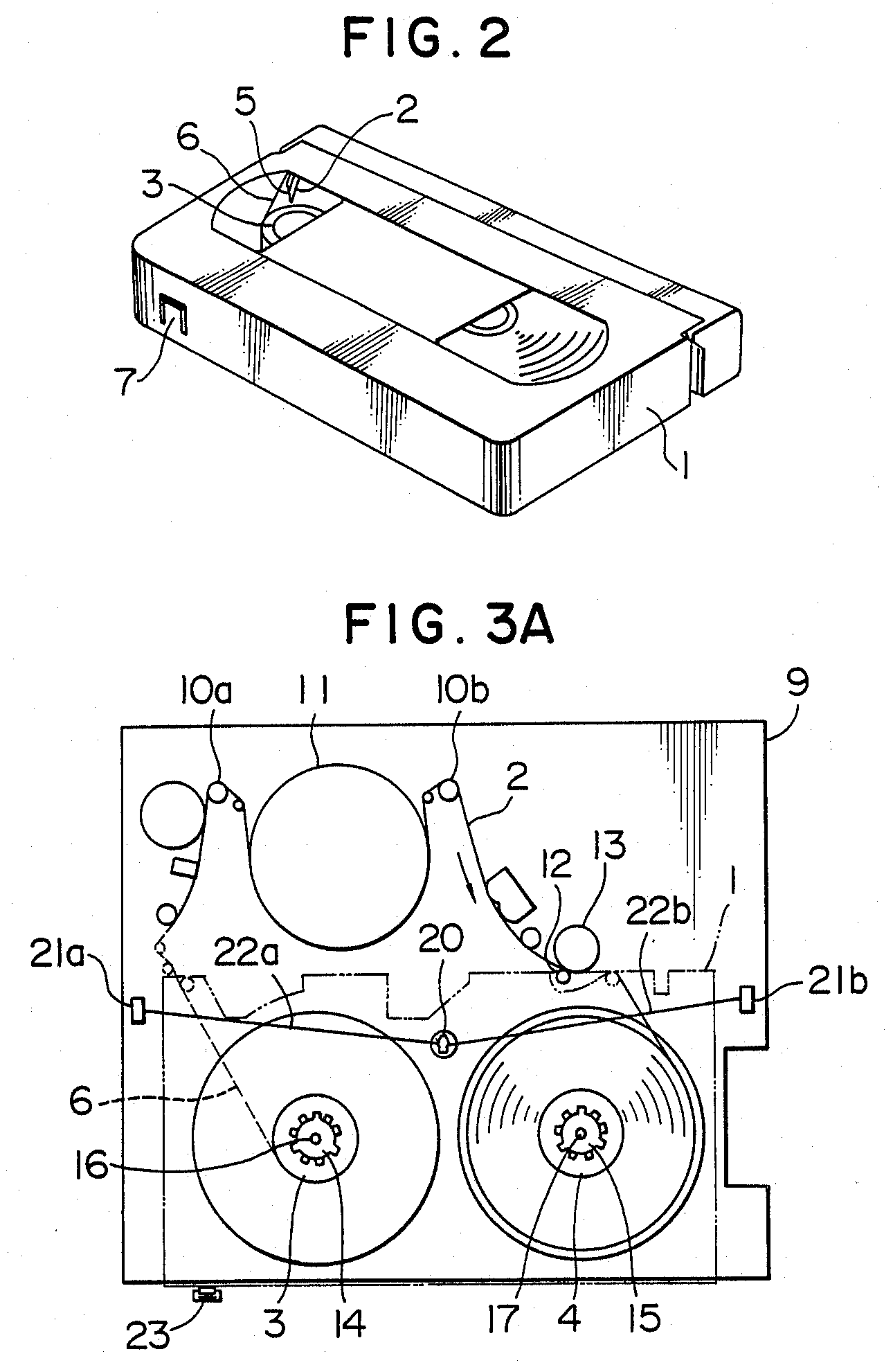
order to permanently store the contents which are recorded on the tape 2, the safety lug 7 may be snapped so as to prevent re-recording (re-erasing) in interlocking relationship with a safety switch which will be described later. The cassette 1 is transported by a cassette loading device, and then loaded in a predetermined position determined by a chassis 9 (the state shown in FIG. 3A).
406:
299:
168:
473:
110:
Referring to FIG. 2, a cassette 1 includes a pair of reels 3 and 4 between which a magnetic tape 2 is passed. The magnetic tape 2 has opposite terminal ends 5 connected to transparent leader taper portions 6, one of which is shown in FIG. 2. The cassette 1 has a safety lug 7 on its back side, and, in
257:
A portion of the disclosure of this patent document contains material which is subject to (copyright or mask work) protection. The (copyright or mask work) owner has no objection to the facsimile reproduction by anyone of the patent document or the patent disclosure, as it appears in the Patent and
117:
Referring specifically to FIGS. 3A, 3B and 3C, the magnetic tape 2 is drawn out of the cassette 1 by the cooperation between tape drawing members 10a and 10b provided on the chassis 9, and is in turn partially wrapped around a cylinder (rotary head drum) 11. The magnetic tape 2 in this state is fed
125:
Referring to FIG. 3A showing the wound-up state of the magnetic tape 2, the light ray 22a emitted from the light-emitting element 20 passes through the transparent leader tape portion 6, and is then detected by the light-receiving element 21a. In this case, since the light ray 22b directed to the
243:, patent applicants and holders may claim copyright in portions of those documents. In those specific cases, applicants are required to identify the portions that are protected under copyright, and are additionally required to state the following within the body of the application and patent:
129:
The aforesaid safety switch 23 is disposed in face-to-face relationship with the safety lug 7 disposed on the cassette 1. If the safety lug 1 is present, the switch 23 is pressed by the safety lug 1 and the switch 23 is depressed to turn on the associated contacts. The thus-generated signal is
121:
Also, the cassette 1 has an opening through which the light-emitting element 20 is inserted, and light rays 22a and 22b emitted from the light-emitting element 20 pass through holes 1a and 1b on opposite sides of the cassette 1, and then detected by the light-receiving elements 21a and 21b,
130:
transmitted to the body of the apparatus and thus recording is enabled. If the safety lug 1 has been snapped, that is, the safety lug 1 is absent, the contacts are maintained in an OFF state and thus recording (erasing) is made unable.
55:
51:
47:
43:
37:
68:
179:
Files should have a summary to inform others of the content, author, source, and date if possible. If you know or have access to such information, please add it to the file page.
262:
The original patent should be checked for the presence of such language before an assumption is made that the contents are in the public domain. This template can be replaced by
421:
328:
196:
250:
313:
541:
546:
495:
366:
266:
472:
467:
59:
32:
106:
FIG. 3A is a top plan view diagrammatically showing the VTR mechanism of the embodiment of the present invention;
340:
248:
246:
258:
Trademark Office patent file or records, but otherwise reserves all (copyright or mask work) rights whatsoever.
320:
182:
Notify the uploader with: {{subst:add-author-I|1=Magnetic video tape recorder diagram Us004809115-003.png}}
551:
360:
388:
491:
376:
373:
If you think that a local copy of this file should be retained, then replace this
Template with
324:
298:
526:
483:
244:
535:
103:
FIG. 2 is a perspective view of the appearance of a typical VHS type tape cassette;
556:
521:
359:
If this file is freely licensed, but otherwise unsuitable for
Commons (e.g. out of
306:
143:
414:
383:
Please ensure that the file has a properly descriptive and unambiguous name
114:
The following is a description of the aforementioned elements and switches.
236:
235:, the contents of United States patents are in the public domain in the US.
440:
Click on a date/time to view the file as it appeared at that time.
363:, still copyrighted in the US), then replace this Template with
400:
293:
226:
221:
162:
379:|reason=<Why a local copy is needed>}}
369:|reason=<Why it can't be moved>}}
73:(1,290 × 1,971 pixels, file size: 44 KB, MIME type:
389:Knowledge:File mover#What files should be renamed?
413:This file was suggested for transfer by a bot (
312:Any user may perform this transfer; refer to
8:
442:
88:
352:Endorse this file for transfer by adding
305:This file is a candidate to be copied to
177:, and may be lacking other information.
519:
99:Magnetic video tape recorder diagram;
517:The following 2 pages use this file:
339:transfer it; repeat violators may be
7:
420:. Please verify that this file is
82:
66:
354:|human=<your username>
314:Knowledge:Moving files to Commons
404:
297:
225:
166:
21:
509:You cannot overwrite this file.
319:If this file has problems with
14:
26:
1:
573:
399:
191:
158:
151:
136:
94:
16:
542:Files lacking an author
502:
424:before transferring it.
547:Images from US patents
367:Do not move to Commons
267:PD-US-patent-no notice
261:
36:Size of this preview:
254:
144:U.S. patent 4,809,115
422:suitable for Commons
60:1,290 × 1,971 pixels
468:19:14, 21 July 2006
91:
42:Other resolutions:
387:transferring; see
347:Other Instructions
331:for Commons, then
327:, or is otherwise
175:author information
89:
56:670 × 1,024 pixels
527:Talk:Helical scan
505:
432:
431:
428:
427:
356:to this Template.
307:Wikimedia Commons
292:
291:
241:In specific cases
212:
211:
200:
197:Reusing this file
187:
186:
183:
173:This file has no
90:File information
564:
500:
499:
480:
419:
408:
407:
401:
380:
370:
355:
301:
294:
286:
283:
280:
277:
271:
265:
229:
228:
222:
194:
181:
170:
169:
163:
146:
92:
78:
76:
63:
52:502 × 768 pixels
48:314 × 480 pixels
44:157 × 240 pixels
38:392 × 599 pixels
572:
571:
567:
566:
565:
563:
562:
561:
532:
531:
511:
506:
489:
488:
486:
478:
434:
433:
411:
405:
395:
394:
374:
364:
353:
348:
288:
284:
281:
278:
275:
269:
263:
238:
220:
214:
207:
193:
180:
178:
167:
142:
132:
108:
101:
87:
80:
74:
72:
65:
64:
41:
12:
11:
5:
570:
568:
560:
559:
554:
549:
544:
534:
533:
530:
529:
524:
515:
514:
507:
504:
503:
501:
484:
481:
477:1,290 × 1,971
475:
470:
465:
461:
460:
457:
454:
451:
448:
445:
438:
437:
430:
429:
426:
425:
409:
397:
396:
393:
392:
381:
371:
361:Commons' scope
357:
349:
346:
345:
343:from editing.
302:
290:
289:
273:
272:in such cases.
230:
219:
216:
210:
209:
201:
189:
188:
185:
184:
171:
160:
156:
155:
153:
149:
148:
138:
134:
133:
122:respectively.
96:
86:
83:
81:
35:
31:
30:
29:
24:
19:
13:
10:
9:
6:
4:
3:
2:
569:
558:
555:
553:
550:
548:
545:
543:
540:
539:
537:
528:
525:
523:
520:
518:
512:
510:
497:
493:
487:
482:
476:
474:
471:
469:
466:
463:
462:
458:
455:
452:
449:
446:
444:
443:
441:
435:
423:
418:
416:
410:
403:
402:
398:
390:
386:
382:
378:
372:
368:
362:
358:
351:
350:
344:
342:
338:
335:this tag and
334:
330:
326:
322:
317:
316:for details.
315:
309:
308:
303:
300:
296:
295:
287:
279:Public domain
268:
260:
259:
253:
252:
249:
247:
245:
242:
237:
234:
231:
224:
223:
217:
215:
208:
205:
202:
198:
190:
176:
172:
165:
164:
161:
157:
154:
150:
147:
145:
139:
135:
131:
127:
123:
119:
115:
112:
107:
104:
100:
97:
93:
84:
79:
70:
69:Original file
61:
57:
53:
49:
45:
39:
34:
28:
25:
23:
20:
18:
15:
552:PD-US-patent
522:Fast forward
516:
508:
439:
436:File history
412:
391:for details.
384:
375:{{
365:{{
336:
332:
318:
311:
304:
274:
270:}}
264:{{
256:
255:
240:
239:
232:
213:
206:
203:
174:
140:
128:
124:
120:
116:
113:
109:
105:
102:
98:
95:Description
67:
22:File history
321:attribution
204:See below.
536:Categories
513:File usage
453:Dimensions
377:Keep local
329:ineligible
251:(archived)
233:In general
192:Permission
27:File usage
485:Omegatron
450:Thumbnail
447:Date/Time
415:User:Fbot
325:copyright
218:Licensing
75:image/png
496:contribs
479:(44 KB)
464:current
459:Comment
341:blocked
159:Author
137:Source
85:Summary
71:
385:before
337:DO NOT
333:remove
285:false
282:false
152:Date
141:From
492:talk
456:User
310:.
17:File
557:VHS
538::
494:|
323:,
276:PD
58:|
54:|
50:|
46:|
40:.
498:)
490:(
417:)
199:)
195:(
77:)
62:.
Text is available under the Creative Commons Attribution-ShareAlike License. Additional terms may apply.
