67:
39:
59:
47:
181:(RJ) family, generally separate wires in a sheath are used. In these applications, the outer sheath is stripped then the wires are inserted into the connector and a special termination tool is used to force the conductors into the contacts. Traditionally these connectors have been used with flat cable which makes it easy to ensure the correct conductors go into the correct slots. Modular connectors used with
31:
221:
164:
Pin 1 is typically indicated on the body of the connector by a red or raised "V" mark. The corresponding wire in a ribbon cable is usually indicated by red coloration, a raised molded ridge, or markings printed onto the cable insulation. On the connector pin 2 is opposite pin 1, pin 3 is next to pin
160:
is designed to be used with multi-contact IDC connectors in such a way that many IDC connections can be made at once, saving time in applications where many connections are needed. These connectors are not designed to be reusable, but can often be re-used if care is taken when removing the cable.
228:
Pins are commonly numbered from pin 1 with odd numbers along one side and the even numbers along the other side. Connectors are categorized by pin spacing in mm (pitch), number of pins, and number of rows. Connectors commonly used in computers include:
149:(power) applications, as can be seen in the illustration. The benefits claimed for their use in these applications include up to 50 percent faster installation, due to the reduction in the stripping, twisting and screwing down processes.
199:
are intended to connect individual conductors punched down into each position in the block with a special punch-down tool. Punch-down terminations are also generally seen in telephone and network connectors, in
321:
For all of the above connectors, the computer manufacturer typically attaches a female IDC connector onto one end of a ribbon cable, and later slides that connector onto a matching male
165:
1 along the length of the connector, and so on. On the cable, the wire connected to pin 2 is next to the wire connected to pin 1 (the red coded wire), and so on.
94:
designed to be connected to the conductor(s) of an insulated cable by a connection process which forces a selectively sharpened blade or blades through the
395:
464:
126:, and others. Although originally designed to connect only solid (single-stranded) conductors, IDC technology was eventually extended to multiple-
544:
507:
627:
145:
and signal connections between parts of an electronic or computer system. However, they are now also used in some domestic and industrial
600:
585:
480:
66:
612:
438:
632:
98:, bypassing the need to strip the conductors of insulation before connecting. When properly made, the connector blade
590:
412:
70:
Australian (dual) power outlet, utilizing insulation displacement to connect mains voltage (230 V) supply conductors
138:
38:
392:
209:
95:
270:
461:
548:
504:
58:
91:
188:
cable require careful arranging of the conductors by hand before inserting them into the connector.
123:
205:
17:
524:
247:
134:
237:
196:
182:
142:
119:
46:
511:
468:
399:
368:
240:
178:
115:
34:
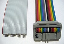
Two ribbon cables: the grey cable is stripped, and the rainbow cable has an IDC connector
358:
353:
621:
363:
296:
127:
484:
348:
234:
185:
157:
99:
570:"FRONTX - Mother-board USB Pin Assignment - USB Header (Pinout) Connection Guide"
338:
280:
201:
146:
545:"national-tech.com – IDC 26 / DB25, Motherboard Parallel Port Connector cable"
373:
326:
322:
343:
111:
30:
393:
http://www.machinedesign.com/BDE/Electrical/bdeee10/bdeee10_3.html#insulate
416:
606:
250:
hard disk drives – 2.00 mm pitch, 44 pins, 2×22 (2 rows of 22 pins)
110:
Modern IDC technology developed after and was influenced by research on
102:
to the conductor, making a theoretically reliable gas-tight connection.
174:
569:
220:
462:
http://updates.clipsal.com/ClipsalOnline/Files/Brochures/A0000102.pdf
595:
505:
national-tech.com – Floppy
Diskdrive pinout and wiring @ pinouts.ru
299:
219:
65:
57:
51:
45:
37:
29:
283:
253:
310:
591:
Brochure on 3M Scotchlok insulation displacement connectors
173:
In some types of telephone and network plug, including the
290:
pitch, 10 pins, 2×5 (2 rows of 5 pins) – sometimes called
243:– 2.54 mm pitch, 40 pins, 2×20 (2 rows of 20 pins)
62:
Connector blades cut insulation into the ribbon cable
525:"RS232 serial motherboard header connector pinout"
224:The "V" mark (circled) shows the position of pin 1
607:A New Type of Very High Reliability Torsion IDC
609:Zierick Manufacturing Corporation white paper.
596:Molex Connectors Explained, as used in Pinball
8:
413:"Insulation Displacing Connector Technology"
601:Insulation Displacement Contact Technology
481:"Videos - Downloads - Clipsal.com - Trade"
54:connectors DE-9 (male) and DA-15 (female)
306:pitch, 26 pins, 2×13 (2 rows of 13 pins)
277:pitch, 34 pins, 2×17 (2 rows of 17 pins)
267:pitch, 68 pins, 2×34 (2 rows of 34 pins)
260:pitch, 50 pins, 2×25 (2 rows of 25 pins)
384:
317:pitch, 10 pins, 2×5 (2 rows of 5 pins)
208:, and in telephone equipment such as
7:
613:AT/Everex wiring for RS-232 COM port
437:Sprovieri, John (February 1, 2001).
415:. Molex Incorporated. Archived from
313:through version 2 on motherboards –
586:IDC Cable, Headers & Connectors
118:technology originally pioneered by
133:Initially, IDCs were seen only in
25:
18:Insulation-displacement connector
76:insulation-displacement contact
1:
391:Basics of Design Engineering
329:on the computer motherboard.
628:Electrical signal connectors
27:Type of electrical connector
169:Telephone and network plugs
84:insulation-piercing contact
649:
603:from Sensors, May 2001.
225:
137:applications, such as
71:
63:
55:
43:
35:
223:
69:
61:
49:
41:
33:
633:Telephone connectors
92:electrical connector
411:Malucci, Robert D.
206:distribution frames
124:Bell Telephone Labs
510:2011-08-02 at the
467:2021-09-28 at the
398:2007-04-03 at the
309:In some instances
286:on motherboards –
226:
139:telecommunications
72:
64:
56:
44:
36:
443:Assembly Magazine
248:notebook computer
197:Punch-down blocks
192:Punch-down blocks
135:extra-low voltage
82:), also known as
16:(Redirected from
640:
574:
573:
566:
560:
559:
557:
556:
547:. Archived from
541:
535:
534:
532:
531:
521:
515:
502:
496:
495:
493:
492:
483:. Archived from
477:
471:
459:
453:
452:
450:
449:
439:"Making Contact"
434:
428:
427:
425:
424:
408:
402:
389:
316:
305:
289:
276:
266:
259:
241:hard disk drives
238:desktop computer
120:Western Electric
42:Connector blades
21:
648:
647:
643:
642:
641:
639:
638:
637:
618:
617:
582:
577:
568:
567:
563:
554:
552:
543:
542:
538:
529:
527:
523:
522:
518:
512:Wayback Machine
503:
499:
490:
488:
479:
478:
474:
469:Wayback Machine
460:
456:
447:
445:
436:
435:
431:
422:
420:
410:
409:
405:
400:Wayback Machine
390:
386:
382:
369:Molex connector
335:
314:
303:
287:
274:
264:
257:
218:
194:
179:registered jack
171:
155:
116:crimp connector
108:
28:
23:
22:
15:
12:
11:
5:
646:
644:
636:
635:
630:
620:
619:
616:
615:
610:
604:
598:
593:
588:
581:
580:External links
578:
576:
575:
561:
536:
516:
497:
472:
454:
429:
403:
383:
381:
378:
377:
376:
371:
366:
361:
359:Berg connector
356:
354:Krone LSA-PLUS
351:
346:
341:
334:
331:
319:
318:
307:
294:
278:
268:
263:SCSI 16-bit –
261:
251:
244:
217:
216:Common layouts
214:
193:
190:
170:
167:
154:
151:
107:
104:
26:
24:
14:
13:
10:
9:
6:
4:
3:
2:
645:
634:
631:
629:
626:
625:
623:
614:
611:
608:
605:
602:
599:
597:
594:
592:
589:
587:
584:
583:
579:
571:
565:
562:
551:on 2011-08-02
550:
546:
540:
537:
526:
520:
517:
513:
509:
506:
501:
498:
487:on 2013-12-14
486:
482:
476:
473:
470:
466:
463:
458:
455:
444:
440:
433:
430:
419:on 2016-02-01
418:
414:
407:
404:
401:
397:
394:
388:
385:
379:
375:
372:
370:
367:
365:
364:JST connector
362:
360:
357:
355:
352:
350:
347:
345:
342:
340:
337:
336:
332:
330:
328:
324:
312:
308:
301:
298:
295:
293:
285:
282:
279:
272:
269:
262:
255:
252:
249:
246:2.5 inch IDE
245:
242:
239:
236:
232:
231:
230:
222:
215:
213:
211:
207:
203:
198:
191:
189:
187:
184:
180:
176:
168:
166:
162:
159:
152:
150:
148:
144:
140:
136:
131:
129:
128:stranded wire
125:
121:
117:
113:
105:
103:
101:
97:
93:
89:
85:
81:
77:
68:
60:
53:
48:
40:
32:
19:
564:
553:. Retrieved
549:the original
539:
528:. Retrieved
519:
514:, 2010-07-25
500:
489:. Retrieved
485:the original
475:
457:
446:. Retrieved
442:
432:
421:. Retrieved
417:the original
406:
387:
349:DC connector
320:
291:
227:
202:patch panels
195:
186:twisted pair
172:
163:
158:Ribbon cable
156:
153:Ribbon cable
132:
109:
87:
83:
79:
75:
73:
339:Vampire tap
271:Floppy disk
147:low voltage
622:Categories
555:2012-06-10
530:2022-06-01
491:2013-04-16
448:2011-03-27
423:2011-03-27
380:References
374:Pin header
327:pin header
323:box header
183:Category 5
143:networking
100:cold-welds
96:insulation
344:Wire wrap
233:3.5 inch
130:as well.
112:wire-wrap
90:), is an
508:Archived
465:Archived
396:Archived
333:See also
297:Parallel
256:8-bit –
177:and the
315:2.54 mm
304:2.54 mm
288:2.54 mm
275:2.54 mm
265:1.27 mm
258:2.54 mm
175:BS 6312
106:History
292:everex
281:Serial
300:DB-25
52:D-sub
284:DE-9
254:SCSI
210:PBXs
204:and
114:and
50:IDC
325:or
311:USB
235:IDE
88:IPC
80:IDC
74:An
624::
441:.
302:–
273:–
212:.
141:,
122:,
572:.
558:.
533:.
494:.
451:.
426:.
86:(
78:(
20:)
Text is available under the Creative Commons Attribution-ShareAlike License. Additional terms may apply.