233:
magnitude of the loop transfer function is 0 dB. It is the additional phase shift that can be tolerated, with no gain change, while remaining stable .Gain margin is the difference (expressed as a positive dB value) between 0 dB and the magnitude of the loop transfer function at the frequency where the phase shift is 180°. It is the amount of gain, which can be increased or decreased without making the system unstable2. For a stable system, both the margins should be positive, or the phase margin should be greater than the gain margin1. For a marginally stable system, the margins should be zero or the phase margin should be equal to the gain margin. You can use Bode plots to graphically determine the gain margin and phase margin of a system. A Bode plot maps the frequency response of the system through two graphs – the Bode magnitude plot (expressing the magnitude in decibels) and the Bode phase plot (expressing the phase shift in degrees).
20:
254:". Often amplifiers are designed to achieve a typical phase margin of 60 degrees. If the typical phase margin is around 60 degrees then the minimum phase margin will typically be greater than 45 degrees. A phase margin of 60 degrees is also a magic number because it allows for the fastest settling time when attempting to follow a voltage step input (a
345:
207:, are measures of stability in closed-loop, dynamic-control systems. Phase margin indicates relative stability, the tendency to oscillate during its damped response to an input change such as a step function. Gain margin indicates absolute stability and the degree to which the system will oscillate, without limit, given any disturbance.
210:
The output signals of all amplifiers exhibit a time delay when compared to their input signals. This delay causes a phase difference between the amplifier's input and output signals. If there are enough stages in the amplifier, at some frequency, the output signal will lag behind the input signal by
241:
In practice, feedback amplifiers must be designed with phase margins substantially in excess of 0°, even though amplifiers with phase margins of, say, 1° are theoretically stable. The reason is that many practical factors can reduce the phase margin below the theoretical minimum. A prime example is
219:
if the fed-back output signal is in phase with the input signal at the frequency at which its open-loop voltage gain equals its closed-loop voltage gain and the open-loop voltage gain is one or greater. The oscillation will occur because the fed-back output signal will then reinforce the input
232:
Phase margin and gain margin are two measures of stability for a feedback control system. They indicate how much the gain or the phase of the system can vary before it becomes unstable. Phase margin is the difference (expressed as a positive number) between 180° and the phase shift where the
211:
one cycle period at that frequency. In this situation, the amplifier's output signal will be in phase with its input signal though lagging behind it by 360°, i.e., the output will have a phase angle of −360°. This lag is of great consequence in amplifiers that use
188:
In the above loop-gain definition, it is assumed that the amplifier input presents zero load. To make this work for non-zero-load input, the output of the feedback network needs to be loaded with an equivalent load for the purpose of determining the
134:
in relation to the input. The PM will be positive but decreasing at frequencies less than the frequency at which inversion sets in (at which PM = 0), and PM is negative (PM < 0) at higher frequencies. In the presence of
143:
exceeds unity (1) guarantees instability. Thus positive PM is a "safety margin" that ensures proper (non-oscillatory) operation of the circuit. This applies to amplifier circuits as well as more generally, to
99:
246:
to achieve a minimum phase margin of 45° or so. This means that at the frequency at which the open and closed loop gains meet, the phase angle is −135°. The calculation is:
181:
More generally, PM is defined as that of the amplifier and its feedback network combined (the "loop", normally opened at the amplifier input), measured at a frequency where the
105:
For example, if the amplifier's open-loop gain crosses 0 dB at a frequency where the phase lag is -135°, then the phase margin of this feedback system is -135° -(-180°) = 45°.
45:(< 0) and -180°, for an amplifier's output signal (relative to its input) at zero dB gain - i.e. unity gain, or that the output signal has the same amplitude as the input.
196:
It is also assumed that the graph of gain vs. frequency crosses unity gain with a negative slope and does so only once. This consideration matters only with reactive and
224:, the critical output phase angle is −180° because the output is fed back to the input through an inverting input which adds an additional −180°.
185:
is unity, and prior to the closing of the loop, through tying the output of the open loop to the input source, in such a way as to subtract from it.
250:
See
Warwick or Stout for a detailed analysis of the techniques and results of compensation to ensure adequate phase margins. See also the article "
488:
549:
458:
431:
314:
304:
130:< 0) varies with frequency, progressively increasing to exceed 180°, at which frequency the output signal becomes inverted, or
534:
524:
51:
529:
483:
262:
for longer and an amplifier with more phase margin will take a longer time to rise to the voltage step's final level.
448:
544:
168:
242:
when the amplifier's output is connected to a capacitive load. Therefore, operational amplifiers are usually
539:
197:
243:
216:
221:
160:
28:
278:
Ringing is the displaying of a decaying oscillation for a portion of the output signal's cycle; see
371:
255:
190:
175:
493:
454:
427:
379:
310:
279:
259:
153:
136:
406:
394:
149:
478:
251:
164:
145:
518:
508:
36:
421:
171:
498:
503:
204:
182:
140:
131:
108:
19:
212:
121:
426:(Second ed.). Singapore: World Scientific. Chapter 5, pp. 137–196.
152:
conditions (e.g. reactive loads). In its simplest form, involving ideal
309:(Second ed.). Cambridge MA: Dr. Robotnic. § 4.33 pp. 242–249.
163:
feedback, the phase margin is measured at the frequency where the
18:
372:
https://www.electrical4u.com/bode-plot-gain-margin-phase-margin/
228:
Phase Margin, Gain margin and relation with feedback stability
200:
feedback networks, as may be the case with active filters.
346:"17.1: Gain Margins, Phase Margins, and Bode Diagrams"
94:{\displaystyle \mathrm {PM} =\varphi -(-180^{\circ })}
54:
258:
design). An amplifier with lower phase margin will
203:Phase margin and its important companion concept,
93:
139:, a zero or negative PM at a frequency where the
450:Handbook of operational amplifier circuit design
8:
220:signal at that frequency. In conventional
82:
55:
53:
295:
271:
447:David F Stout & Kaufman M (1976).
402:
389:
388:
377:
109:Bode plot#Gain margin and phase margin
7:
340:
338:
167:of the amplifier equals the desired
303:Paul Horowitz & Hill W (1989).
35:(PM) is the difference between the
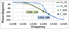
23:Bode plot illustrating phase margin
423:An introduction to control systems
215:. The reason: the amplifier will
59:
56:
16:Parameter of electronic amplifiers
14:
489:Routh–Hurwitz stability criterion
509:Step response & phase margin
124:phase lag (relative to input,
88:
72:
1:
504:Bode plots & phase margin
453:. NY: McGraw-Hill. Sec. 3–4.
484:Nyquist stability criterion
566:
550:Classical control theory
350:Engineering LibreTexts
306:The art of electronics
248:-135° - (-180°) = 45°.
222:operational amplifiers
165:open-loop voltage gain
95:
24:
535:Electronic amplifiers
525:Electrical parameters
96:
29:electronic amplifiers
22:
159:amplifiers with non-
52:
530:Electronic feedback
420:K Warwick (1996).
193:of the loop gain.
191:frequency response
91:
25:
545:Signal processing
499:Root locus method
494:Ringing artifacts
401:Missing or empty
387:External link in
280:ringing artifacts
154:negative feedback
137:negative feedback
111:for more details.
557:
465:
464:
444:
438:
437:
417:
411:
410:
404:
398:
392:
391:
385:
383:
375:
367:
361:
360:
358:
357:
342:
333:
327:
321:
320:
300:
283:
276:
249:
148:, under various
129:
112:
100:
98:
97:
92:
87:
86:
62:
44:
565:
564:
560:
559:
558:
556:
555:
554:
515:
514:
513:
474:
469:
468:
461:
446:
445:
441:
434:
419:
418:
414:
400:
386:
376:
369:
368:
364:
355:
353:
344:
343:
336:
328:
324:
317:
302:
301:
297:
292:
287:
286:
277:
273:
268:
247:
239:
230:
125:
118:
106:
78:
50:
49:
40:
17:
12:
11:
5:
563:
561:
553:
552:
547:
542:
540:Systems theory
537:
532:
527:
517:
516:
512:
511:
506:
501:
496:
491:
486:
481:
479:BIBO stability
475:
473:
470:
467:
466:
459:
439:
432:
412:
362:
334:
322:
315:
294:
293:
291:
288:
285:
284:
270:
269:
267:
264:
252:Pole splitting
238:
235:
229:
226:
146:active filters
120:Typically the
117:
114:
103:
102:
90:
85:
81:
77:
74:
71:
68:
65:
61:
58:
15:
13:
10:
9:
6:
4:
3:
2:
562:
551:
548:
546:
543:
541:
538:
536:
533:
531:
528:
526:
523:
522:
520:
510:
507:
505:
502:
500:
497:
495:
492:
490:
487:
485:
482:
480:
477:
476:
471:
462:
460:0-07-061797-X
456:
452:
451:
443:
440:
436:. (pb). (hc).
435:
433:981-02-2597-0
429:
425:
424:
416:
413:
408:
396:
381:
373:
366:
363:
351:
347:
341:
339:
335:
331:
326:
323:
318:
316:0-521-37095-7
312:
308:
307:
299:
296:
289:
281:
275:
272:
265:
263:
261:
257:
253:
245:
236:
234:
227:
225:
223:
218:
214:
208:
206:
201:
199:
194:
192:
186:
184:
179:
177:
173:
170:
166:
162:
158:
155:
151:
147:
142:
138:
133:
128:
123:
115:
113:
110:
83:
79:
75:
69:
66:
63:
48:
47:
46:
43:
38:
34:
30:
21:
449:
442:
422:
415:
390:|title=
365:
354:. Retrieved
352:. 2019-01-30
349:
329:
325:
305:
298:
274:
240:
231:
209:
202:
195:
187:
180:
156:
126:
119:
104:
41:
33:phase margin
32:
26:
256:Butterworth
244:compensated
205:gain margin
169:closed-loop
519:Categories
403:|url=
356:2023-12-25
290:References
332:, p. 245.
266:Footnotes
217:oscillate
183:loop gain
141:loop gain
132:antiphase
122:open-loop
84:∘
76:−
70:−
67:φ
472:See also
380:cite web
237:Practice
213:feedback
174:voltage
161:reactive
157:voltage
457:
430:
313:
198:active
116:Theory
31:, the
37:phase
455:ISBN
428:ISBN
407:help
395:help
330:Ibid
311:ISBN
260:ring
176:gain
150:load
107:See
39:lag
80:180
27:In
521::
399:;
384::
382:}}
378:{{
374:".
348:.
337:^
178:.
172:DC
463:.
409:)
405:(
397:)
393:(
370:"
359:.
319:.
282:.
127:φ
101:.
89:)
73:(
64:=
60:M
57:P
42:φ
Text is available under the Creative Commons Attribution-ShareAlike License. Additional terms may apply.