280:
155:
22:
187:
with numbers or letters printed onto them and collected in small, pocket sized booklets. A number strip would be peeled out and wrapped around the wire near the end. Wire numbers were made up of a series of the number strips so wire 1051 would be four strips. There are also pocket sized printers that print onto an adhesive backed label that can be wrapped around the wire.
179:. The conditions that represent the inputs are connected in series, parallel, or series-parallel to obtain the logic required to drive the output. The relay logic circuit forms an electrical schematic diagram for the control of input and output devices. Relay logic diagrams represent the physical interconnection of devices.
228:
182:
Each rung would have a unique identifying reference number and the individual wires on that rung would have wire numbers as a derivative of the rung number. Thus, if a rung was labelled as 105, the first independent wire would be 1051, the second as 1052, and so forth. A wire would be named for the
186:
When the rack was manufactured, as a wire was installed, each end would be marked with wire labels (a.k.a. wire markers). This also applied for pulling wire into the factory through conduit or in trays where each wire would have corresponding numbers. Wire labels were typically pieces of white tape
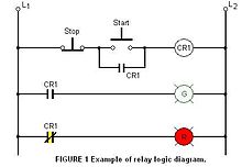
224:. When the START button is pressed, the control relay energizes and its associated contacts change state. The green pilot light is now ON and the red lamp is OFF. When the STOP button is pressed, the contacts return to their resting state, the red pilot light is ON, and the green switches OFF.
170:
consisting of lines, or rungs, in which each line or rung must have continuity to enable the output device. A typical circuit consists of a number of rungs, with each rung controlling an output. This output is controlled by a combination of input or output conditions, such as input
239:
In many cases, it is possible to design a relay logic diagram directly from the narrative description of a control event sequence. In general, the following suggestions apply to designing a relay logic diagram:
276:, but have been progressively superseded with modern solid-state controls in recent years. Relay logic is also used for controlling and automation purposes in electro-hydraulics and electro-pneumatics.
253:
3. Determine the sequence of operations to be performed. List the sequence of operational steps in as much detail as possible. Write out the sequence in sentences, or put them in table form.
183:
top most rung to which it connected, even if it branched to lower rungs. When designing a system, it was common practice to skip numbers for the rungs to allow later additions as required.
193:
1. The two vertical lines that connect all devices on the relay logic diagram are labeled L1 and L2. The space between L1 and L2 represents the voltage of the control circuit.
166:
for relay logic circuits are often called line diagrams, because the inputs and outputs are essentially drawn in a series of lines. A relay logic circuit is an
203:
3. Control devices are always shown between L1 and the output device. Control devices may be connected either in series or in parallel with each other.
206:
4. Devices which perform a STOP function are usually connected in series, while devices that perform a START function are connected in parallel.
200:
that are to be included must be shown between the output device and L2; otherwise, the output device must be the last component before L2.
345:
217:
contact would appear as a normally open device. All contacts associated with a device will change state when the device is energized.
113:
264:
A major application of relay logic is the control of routing and signalling on railways. This safety critical application uses
47:
329:
94:
66:
43:
272:
are another common application - large relay logic circuits were employed from the 1930s onward to replace the human
32:
292:
Most relay logic diagrams are in "ladder logic" form. Systems using relay logic diagrams in other forms include the
73:
51:
36:
80:
220:
Figure 1 shows a typical relay logic diagram. In this circuit, a STOP/START station is used to control two
62:
305:
133:
297:
250:
of the operation process. Make sure all the components of the system are present in the drawing.
167:
163:
273:
247:
154:
317:
309:
301:
210:
87:
293:
339:
214:
176:
279:
313:
265:
149:
268:
to ensure conflicting routes can never be selected and helps reduce accidents.
221:
197:
21:
227:
269:
172:
137:
278:
256:
4. Write the relay logic diagram from the sequence of operations.
226:
153:
209:
5. Electrical devices are shown in their normal conditions. An
15:
332:- the modern replacement for complex relay logic in industry
136:
in electrical control circuits by using several electrical
190:
The basic format for relay logic diagrams is as follows:
196:2. Output devices are always connected to L2. Any
213:contact would be shown as normally closed, and an
126:Arrangement of relays used to control machinery
8:
304:by relays, and the designs for the various
50:. Unsourced material may be challenged and
114:Learn how and when to remove this message
243:1. Define the process to be controlled.
140:wired in a particular configuration.
7:
48:adding citations to reliable sources
14:
312:. Design tools for these include
20:
283:Figure 1 from Vernam's patent.
1:
330:Programmable logic controller
306:electro-mechanical computers
158:Example Ladder Logic Diagram
132:is a method of implementing
362:
346:Electromagnetic components
288:Other kinds of relay logic
147:
296:, the many 20th century
300:that controlled their
284:
231:
159:
294:Vernam cipher machine
282:
230:
157:
198:electrical overloads
44:improve this article
298:telephone exchanges
134:combinational logic
285:
235:Relay logic design
232:
168:electrical network
164:schematic diagrams
160:
302:crossbar switches
274:elevator operator
124:
123:
116:
98:
353:
119:
112:
108:
105:
99:
97:
56:
24:
16:
361:
360:
356:
355:
354:
352:
351:
350:
336:
335:
326:
318:Boolean algebra
310:Harvard Mark II
290:
262:
237:
152:
146:
127:
120:
109:
103:
100:
57:
55:
41:
25:
12:
11:
5:
359:
357:
349:
348:
338:
337:
334:
333:
325:
322:
308:including the
289:
286:
261:
258:
236:
233:
177:control relays
148:Main article:
145:
142:
125:
122:
121:
28:
26:
19:
13:
10:
9:
6:
4:
3:
2:
358:
347:
344:
343:
341:
331:
328:
327:
323:
321:
319:
315:
314:Karnaugh maps
311:
307:
303:
299:
295:
287:
281:
277:
275:
271:
267:
259:
257:
254:
251:
249:
244:
241:
234:
229:
225:
223:
218:
216:
212:
207:
204:
201:
199:
194:
191:
188:
184:
180:
178:
174:
169:
165:
156:
151:
143:
141:
139:
135:
131:
118:
115:
107:
104:December 2014
96:
93:
89:
86:
82:
79:
75:
72:
68:
65: –
64:
63:"Relay logic"
60:
59:Find sources:
53:
49:
45:
39:
38:
34:
29:This article
27:
23:
18:
17:
291:
266:interlocking
263:
260:Applications
255:
252:
245:
242:
238:
222:pilot lights
219:
208:
205:
202:
195:
192:
189:
185:
181:
161:
150:ladder logic
144:Ladder logic
129:
128:
110:
101:
91:
84:
77:
70:
58:
42:Please help
30:
130:Relay logic
246:2. Draw a
74:newspapers
270:Elevators
31:does not
340:Category
324:See also
173:switches
88:scholar
52:removed
37:sources
248:sketch
138:relays
90:
83:
76:
69:
61:
95:JSTOR
81:books
316:and
175:and
162:The
67:news
35:any
33:cite
46:by
342::
320:.
215:NO
211:NC
117:)
111:(
106:)
102:(
92:·
85:·
78:·
71:·
54:.
40:.
Text is available under the Creative Commons Attribution-ShareAlike License. Additional terms may apply.