56:
20:
138:
95:. Programmers use a structure chart to build a program in a manner similar to how an architect uses a blueprint to build a house. In the design stage, the chart is drawn and used as a way for the client and the various software designers to communicate. During the actual building of the program (implementation), the chart is continually referred to as "the master-plan".
128:
and the lowest manageable level. An accurate and complete structure chart is the key to the determination of the configuration items (CI), and a visual representation of the configuration system and the internal interfaces among its CIs. During the configuration control process, the structure chart
145:
According to Wolber (2009), "a structure chart can be developed starting with the creating of a structure, which places the root of an upside-down tree which forms the structure chart. The next step is to conceptualize the main sub-tasks that must be performed by the program to solve the problem.
146:
Next, the programmer focuses on each sub-task individually, and conceptualizes how each can be broken down into even smaller tasks. Eventually, the program is broken down to a point where the leaves of the tree represent simple methods that can be coded with just a few program statements".
59:
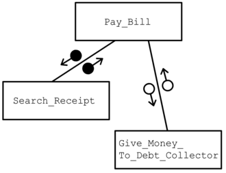
This hierarchy chart represents data passing between two modules. When the module Pay_Bill is executed, the pseudocode checks if the bill is already paid by searching for the payment receipt (execute Search_Receipt). If the receipt is not found then it will execute the module
87:. As a design tool, they aid the programmer in dividing and conquering a large software problem, that is, recursively breaking a problem down into parts that are small enough to be understood by a human brain. The process is called
149:
In practice, see figure, first it is checked if a structure chart has been developed already. If so an expert needs to review it to ensure it represents the current structure and if not, updates the chart where needed.
47:
to arrange program modules into a tree. Each module is represented by a box, which contains the module's name. The tree structure visualizes the relationships between modules.
347:
285:
184:
335:
72:, and lines that connect them. The lines represent the connection and or ownership between activities and subactivities as they are used in
159:
341:
141:
A process flow diagram describing the construction of a structure chart by a so-called
Subject Matter Experts (SME).
370:
83:
structure charts, according to Wolber (2009), "are used to specify the high-level design, or architecture, of a
214:
194:
92:
288:: Supplementary Notes Structure Charts and Bottom-up Implementation: Java Version. Accessed 8 November 2009
108:
whether each identifiable function is a manageable entity or should be broken down into smaller components.
164:
117:
44:
252:
169:
36:
121:
32:
189:
80:
120:, but other representations are allowable. The representation must describe the breakdown of the
73:
137:
19:
84:
55:
365:
129:
is used to identify CIs and their associated artifacts that a proposed change may impact.
88:
65:
43:
which shows the breakdown of a system to its lowest manageable levels. They are used in
318:
174:
359:
116:
associated elements that comprise a run stream or thread. It is often developed as a
237:
IRS Resources Part 2. Information
Technology Chapter 27. Configuration Management
308:
105:
number of readily identifiable functions and modules within each function and
125:
215:
Sandia
Software Guidelines Volume 5 Tools, Techniques, and Methodologies
113:
68:
tool, constructed of squares representing the different modules in the
69:
301:
Sarah Brooks (1981). "Structure Charts and Basic
Programming". in:
54:
40:
179:
270:
New Trends in
Software Methodologies, Tools and Techniques
240:
243:
14 November 2008. No longer online 8 November 2009.
60:Give_Money_To_Debt_Collector to finish the job.
8:
313:Structured Analysis and System Specification
235:IRS (2008) "Configuration Management" In:
102:the size and complexity of the system, and
257:Structured Techniques: The Basis for Case
185:Structured Analysis and Design Technique
136:
18:
325:, Yourdon Press Computing Series, 1999,
206:
305:, v15 n2 p. 107-112 Spring 1981.
280:
278:
231:
229:
227:
225:
223:
213:Sandia National Laboratories (1992).
7:
160:Computer-aided software engineering
112:A structure chart is also used to
14:
268:H. Fujita & V. Gruhn (2004).
23:Example of a Structured Chart.
1:
342:State Court Structure Charts
217:SANDIA REPORTS 85–2348qUC–32
133:Structure chart construction
255:, Carma L. McClure (1988).
387:
323:Modern Structured Analysis
98:A structure chart depicts
195:Work breakdown structure
93:functional decomposition
344:, a series of examples.
66:top-down modular design
64:A structure chart is a
259:. Prentice Hall. p.56.
165:System context diagram
142:
61:
45:structured programming
24:
284:David Wolber (2009) "
170:Decomposition diagram
140:
58:
37:organizational theory
22:
122:configuration system
118:hierarchical diagram
33:software engineering
190:Warnier/Orr diagram
81:structured analysis
74:organization charts
143:
62:
25:
378:
371:Systems analysis
348:Structure Charts
336:Structure charts
315:. Prentice Hall.
289:
286:Structure Charts
282:
273:
266:
260:
250:
244:
233:
218:
211:
85:computer program
386:
385:
381:
380:
379:
377:
376:
375:
356:
355:
332:
298:
296:Further reading
293:
292:
283:
276:
267:
263:
251:
247:
234:
221:
212:
208:
203:
156:
135:
89:top-down design
53:
29:structure chart
17:
12:
11:
5:
384:
382:
374:
373:
368:
358:
357:
352:
351:
345:
339:
331:
330:External links
328:
327:
326:
319:Edward Yourdon
316:
306:
297:
294:
291:
290:
274:
261:
245:
239:. Accessed at
219:
205:
204:
202:
199:
198:
197:
192:
187:
182:
177:
175:Function model
172:
167:
162:
155:
152:
134:
131:
110:
109:
106:
103:
52:
49:
15:
13:
10:
9:
6:
4:
3:
2:
383:
372:
369:
367:
364:
363:
361:
354:
349:
346:
343:
340:
337:
334:
333:
329:
324:
320:
317:
314:
310:
307:
304:
303:MATYC Journal
300:
299:
295:
287:
281:
279:
275:
271:
265:
262:
258:
254:
249:
246:
242:
238:
232:
230:
228:
226:
224:
220:
216:
210:
207:
200:
196:
193:
191:
188:
186:
183:
181:
178:
176:
173:
171:
168:
166:
163:
161:
158:
157:
153:
151:
147:
139:
132:
130:
127:
123:
119:
115:
107:
104:
101:
100:
99:
96:
94:
90:
86:
82:
77:
75:
71:
67:
57:
50:
48:
46:
42:
38:
34:
30:
21:
353:
322:
312:
302:
269:
264:
256:
253:James Martin
248:
236:
209:
148:
144:
111:
97:
78:
63:
28:
26:
309:Tom DeMarco
360:Categories
201:References
126:subsystems
338:Overview.
272:. Page 6.
321:(1999).
311:(1979).
154:See also
51:Overview
31:(SC) in
350:(.doc).
241:IRS.GOV
114:diagram
366:Charts
70:system
124:into
91:, or
41:chart
39:is a
16:Chart
180:HIPO
35:and
79:In
362::
277:^
222:^
76:.
27:A
Text is available under the Creative Commons Attribution-ShareAlike License. Additional terms may apply.