328:, and travels to the Front of House position. Here, the still-mic-level signal enters into a microphone preamplifier, which boosts the signal voltage to line level. For this example, the microphone preamplifier is built into a mixing board. It is typical for a mixing board to include a line trim after the preamplifier. This allows the amplitude of the now line-level signal to be adjusted. This may be done for artistic or technical reasons. A typical application for the line trim is attenuating signals that were intentionally amplified too much by the microphone preamplifier. Over amplifying the signal can cause the preamplifier to distort, which can under certain circumstances produce a desirable sound.
276:
236:
264:
301:
317:
253:
180:
36:
287:
249:
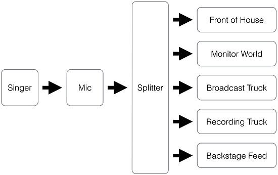
The signal from each microphone is therefore being sent to five places; the house sound system, the in-ear monitor system for the performers, the broadcast system, the recording system, and to the lobby, restrooms, and backstage areas so that people can hear the performance while outside the performance area.
155:
Feedback, also called "Howl-Round," occurs when the output of a device is accidentally connected to its input. If the device is amplifying the signal, then the amplified output will be fed back into the input, where it will be amplified again and sent to the output, where it will return to the input,
331:
After the line trim, the signal is processed by the mixing board's EQ, filter, compressor, limiter, de-esser, delay, reverb, and any other signal processing features the mixing board has available and that the mix engineer chooses to use. The processed signal is then sent to the mix bus, where it is
226:
The signal flow begins as in the previous example; singer, microphone, microphone preamplifier, EQ, and compressor. For this example, this signal then flows into a mixing board, which allows the signal to be routed to various outputs. The mixing board includes facilities for a main mix bus, which we
195:
systems, computer fans, traffic noise, elevators, plumbing, etc. These noise sources can also be picked up by the microphone. It is therefore important to optimize the acoustical signal/noise ratio at the microphone. This can be accomplished by reducing the amplitude of unwanted noise (for example,
248:
In this example, we will explore the signal flow of a hypothetical rock concert. For our example, this concert not only has a live audience, it is also being broadcast on live TV, and it is being recorded, with copies of the recording being sold to the public immediately after the concert is over.
199:
After the microphone, the signal passes down a cable to the microphone preamplifier, which amplifies the microphone signal to line level. This is important because a line-level signal is necessary to drive the input circuitry of any further processing equipment down the chain, which will generally
167:
The first component in the signal flow is the CD player, which produces the signal. The output of the CD player is connected to an input on a receiver. In a typical home stereo system, this connection will be analog and unbalanced at consumer line-level of -10dBV using RCA connectors. By selecting
271:
The in-ear monitor system will be controlled by a monitor mix engineer located in the wing on one side of the stage. It is necessary that the monitor mix engineer be able to communicate with the performers, so being in close proximity to them is essential. The monitor mix position is often called
204:
For the purposes of this example, the output of the microphone preamplifier is then sent to an EQ, where the timbre of the sound may be manipulated for artistic or technical purposes. Examples of artistic purposes include making the singer sound "brighter," "darker," "more forward," "less nasal,"
146:
In typical home stereo systems, the signal flow is usually short and simple, with only a few components. However, in recording studios and performance venues, the signal flow can often be quite complicated, with a large number of components, each of which may cause the signal to fail to reach its
312:
will be used. The microphone splitter serves several purposes; it will split the signal 5-ways, provide phantom power for condenser microphones and active DI boxes, and it will provide isolation between the 5 outputs, preventing ground loops. Preventing ground loops is an extremely important
168:
the proper input on the receiver, the signal is routed internally to an amplifier which boosts the signal voltage from line-level to the voltage required by the speakers. The output of the amplifier is then connected to speakers, which convert the electrical signal into acoustical sound.
313:
function, as the severity of ground loops typically increases with distance. In a large network of interconnected sound systems, such as the one in this example, ground loops could become dangerously severe. Isolation to prevent ground loops is therefore vitally important.
335:
The mix is then routed to one of the mixing boards outputs, and flows into a loudspeaker controller. This device processes the signal to optimize it for the sound system installed in the performance venue. It then flows into a rack of amplifiers, and then to the speakers.
196:
turning off the HVAC system while recording), or by taking advantage of the inverse-square law; by moving the microphone closer to the signal source and farther away from any noise sources, the signal/noise ratio is increased.
227:
will send to the house sound system, a monitor mix bus, which we will use to create a monitor mix for the singer, and an auxiliary mix bus, which we will use to create a second mix to be sent to the lobby and nursery.
205:
etc. Examples of technical purposes include reducing unwanted low-frequency rumble from HVAC systems, compensating for high-frequency loss caused by distant microphone placement, etc.
139:
signal takes from source to output. The concept of audio signal flow is closely related to the concept of audio gain staging; each component in the signal flow can be thought of as a
176:
The exact series of elements in a signal flow will vary from system to system. The following example depicts a typical signal flow for recording a vocalist in a recording studio.
260:
The house sound system will be controlled from the "Front of House" position, also called the "Mix position." This position is usually located behind the audience.
208:
The output of the EQ will then be sent to a compressor, which is a device that manipulates the dynamic range of a signal for either artistic or technical reasons.
211:
The output of the compressor is then sent to an analog-to-digital converter, which converts the signal to a digital format, allowing the signal to be sent to a
187:
The first element in the signal flow is the vocalist, which produces the signal. This signal propagates acoustically to the microphone according to the
147:
desired output. Knowing each component in the signal flow becomes increasingly difficult and important as system size and complexity increases.
191:, where it is converted by a transducer into an electrical signal. Other objects may also produce sound in the acoustical environment, such as
392:
53:
119:
100:
156:
be amplified again, and sent to the output, ad infinitum. An understanding of signal flow is important in preventing feedback.
72:
57:
324:
Let's begin by tracing the signal path from the splitter to the audience. The signal leaves the splitter, typically via an
297:
For this example, the lobby, restroom, and backstage mix will be controlled by an assistant stage manager from backstage.
79:
283:
The broadcast mix will be controlled from a broadcast truck, located in the parking lot behind the performance venue.
417:
86:
46:
164:
The following example will trace the signal flow of a typical home stereo system while playing back an audio CD.
68:
275:
332:
combined with all the other signals coming from the stage. The balance of signals is controlled by faders.
325:
355:
309:
188:
93:
388:
384:
212:
294:
The recording system will be located in another truck, located next to the broadcast truck.
252:
179:
263:
235:
200:
not be able to accept the extremely low-voltage signal produced by a typical microphone.
411:
377:
300:
316:
223:
The following example traces the signal flow of a vocalist performing in a church.
35:
345:
290:
Arena
Television OB8 working for the BBC at Wimbledon Tennis Championships, UK
140:
17:
286:
350:
315:
299:
285:
274:
262:
251:
234:
178:
136:
192:
29:
60:. Unsourced material may be challenged and removed.
376:
308:To facilitate this 5-way split, a device called a
256:Overview diagram of Signal Flow for this example.
27:Path an audio signal takes from source to output
239:A diagram of a typical signal flow for a band
172:Single vocalist recording signal flow example
8:
267:The view from the Front of House Position.
244:Broadcast performance signal flow example
120:Learn how and when to remove this message
383:(2nd ed.). Peachpit Press. p.
367:
219:Vocalist live sound signal flow example
379:Pro Tools 6 for Macintosh and Windows
7:
279:An example of a monitor mix position
58:adding citations to reliable sources
320:An example of a microphone splitter
25:
34:
45:needs additional citations for
1:
215:device, such as a computer.
434:
183:Singer Signal Flow Example
231:Band signal flow example
375:Steven Roback (2004).
321:
305:
291:
280:
268:
257:
240:
184:
326:Audio multicore cable
319:
303:
289:
278:
266:
255:
238:
182:
304:Stage managers panel
54:improve this article
356:Microphone splitter
310:microphone splitter
160:CD playback example
69:"Audio signal flow"
399:audio signal flow.
322:
306:
292:
281:
269:
258:
241:
189:Inverse-square law
185:
418:Audio engineering
394:978-0-321-21315-0
272:"monitor world."
213:digital recording
133:Audio signal flow
130:
129:
122:
104:
16:(Redirected from
425:
402:
401:
382:
372:
125:
118:
114:
111:
105:
103:
62:
38:
30:
21:
433:
432:
428:
427:
426:
424:
423:
422:
408:
407:
406:
405:
395:
374:
373:
369:
364:
342:
246:
233:
221:
203:
174:
162:
153:
135:is the path an
126:
115:
109:
106:
63:
61:
51:
39:
28:
23:
22:
15:
12:
11:
5:
431:
429:
421:
420:
410:
409:
404:
403:
393:
366:
365:
363:
360:
359:
358:
353:
348:
341:
338:
245:
242:
232:
229:
220:
217:
173:
170:
161:
158:
152:
149:
128:
127:
42:
40:
33:
26:
24:
14:
13:
10:
9:
6:
4:
3:
2:
430:
419:
416:
415:
413:
400:
396:
390:
386:
381:
380:
371:
368:
361:
357:
354:
352:
349:
347:
344:
343:
339:
337:
333:
329:
327:
318:
314:
311:
302:
298:
295:
288:
284:
277:
273:
265:
261:
254:
250:
243:
237:
230:
228:
224:
218:
216:
214:
209:
206:
201:
197:
194:
190:
181:
177:
171:
169:
165:
159:
157:
150:
148:
144:
142:
138:
134:
124:
121:
113:
102:
99:
95:
92:
88:
85:
81:
78:
74:
71: –
70:
66:
65:Find sources:
59:
55:
49:
48:
43:This article
41:
37:
32:
31:
19:
398:
378:
370:
334:
330:
323:
307:
296:
293:
282:
270:
259:
247:
225:
222:
210:
207:
202:
198:
186:
175:
166:
163:
154:
145:
132:
131:
116:
107:
97:
90:
83:
76:
64:
52:Please help
47:verification
44:
18:Signal flow
346:Gain stage
141:gain stage
80:newspapers
110:June 2020
412:Category
340:See also
151:Feedback
94:scholar
391:
351:Reverb
96:
89:
82:
75:
67:
362:Notes
137:audio
101:JSTOR
87:books
389:ISBN
193:HVAC
73:news
385:303
56:by
414::
397:.
387:.
143:.
123:)
117:(
112:)
108:(
98:·
91:·
84:·
77:·
50:.
20:)
Text is available under the Creative Commons Attribution-ShareAlike License. Additional terms may apply.