367:
standing waves. Depending upon the drive unit and quantity – and various physical properties – of absorbent material, the amount of taper will be adjusted during the design process to tune the duct to remove irregularities in its response. The internal partitioning provides substantial bracing for the entire structure, reducing cabinet flexing and colouration. The inside faces of the duct or line, are treated with an absorbent material to provide the correct termination with frequency to load the drive unit as a TL. A theoretically perfect TL would absorb all frequencies entering the line from the rear of the drive unit but remains theoretical, as it would have to be infinitely long. The physical constraints of the real world, demand that the length of the line must often be less than 4 meters before the cabinet becomes too large for any practical applications, so not all the rear energy can be absorbed by the line. In a realized TL, only the upper bass is TL loaded in the true sense of the term (i.e. fully absorbed); the low bass is allowed to freely radiate from the vent in the cabinet. The line therefore effectively works as a low-pass filter, another crossover point in fact, achieved acoustically by the line and its absorbent filling. Below this “crossover point” the low bass is loaded by the column of air formed by the length of the line. The length is specified to reverse the phase of the rear output of the drive unit as it exits the vent. This energy combines with the output of the bass unit, extending its response and effectively creating a second driver.
268:
that heavily damped lines could reduce the velocity of sound by as much as 50%, although 35% is typical in medium damped lines. Bradbury's tests were carried out using fibrous materials, typically longhaired wool and glass fibre. These kinds of materials, however, produce highly variable effects that are not consistently repeatable for production purposes. They are also liable to produce inconsistencies due to movement, climatic factors and effects over time. High-specification acoustic foams, developed by loudspeaker manufacturers such as PMC, with similar characteristics to longhaired wool, provide repeatable results for consistent production. The density of the polymer, the diameter of the pores and the sculptured profiling are all specified to provide the correct absorption for each speaker model. Quantity and position of the foam is critical to engineer a low-pass acoustic filter that provides adequate attenuation of the upper bass frequencies, whilst allowing an unimpeded path for the low bass frequencies.
264:
extremely light and flexible, having very compliant suspensions. Whilst performing well in a reflex design, these characteristics do not match the demands of a TL design. The drive unit is effectively coupled to a long column of air which has mass. This lowers the resonant frequency of the drive unit, negating the need for a highly compliant device. Furthermore, the column of air provides greater force on the driver itself than a driver opening onto a large volume of air (in simple terms it provides more resistance to the driver's attempt to move it), so to control the movement of air requires an extremely rigid cone, to avoid deformation and consequent distortion.
301:(p483-486) magazine. The article postulated that energy from the rear of a driver unit could be essentially absorbed, without damping the cone's motion or superimposing internal reflections and resonance, so Bailey and Radford reasoned that the rear wave could be channeled down a long pipe. If the acoustic energy was absorbed, it would not be available to excite resonances. A pipe of sufficient length could be tapered, and stuffed so that the energy loss was almost complete, minimizing output from the open end. No broad consensus on the ideal taper (expanding, uniform cross-section, or contracting) has been established.
22:
129:
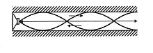
bass driver and vent is in phase in the pass band until the frequency approaches the quarter wavelength, when the relationship reaches 90 degrees as shown. However, by this time the vent is producing most of the output (Fig. 2). Because the line is operating over several octaves with the drive unit, cone excursion is reduced, providing higher SPL's and lower distortion levels, compared with reflex and infinite baffle designs.
361:"I believe that speakers should preserve the integrity of the signal waveform and the Audio Perfectionist Journal has presented a great deal of information about the importance of time domain performance in loudspeakers. I’m not the only one who appreciates time- and phase-accurate speakers but I have been virtually the only advocate to speak out in print in recent years. There’s a reason for that."
277:
121:
113:
288:). Benjamin Olney who worked for Stromberg-Carlson was the inventor of the Acoustical Labyrinth and wrote an article for the Journal of the Acoustic Society of America in October of 1936 entitled "A Method of Eliminating Cavity Resonance, Extending Low Frequency Response and Increasing Acoustic Damping in Cabinet Type Loudspeakers" see
104:
substitution of pressure for voltage, and volume particle velocity for current, the equations are essentially the same. Electrical transmission lines can be used to describe acoustic tubes and ducts, provided the frequency of the waves in the tube is below the critical frequency, such that they are purely planar.
267:
The introduction of the absorption materials reduces the velocity of sound through the line, as discovered by Bailey in his original work. Bradbury published his extensive tests to determine this effect in a paper in the
Journal of the Audio Engineering Society (JAES) in 1976 and his results agreed
103:
frequencies and avoid distortion. The comparison between an acoustic duct and an electrical transmission line is useful in "lumped-element" modeling of acoustical systems, in which acoustic elements like volumes, tubes, pistons, and screens can be modeled as single elements in a circuit. With the
128:
Phase inversion is achieved by selecting a length of line that is equal to the quarter wavelength of the target lowest frequency. The effect is illustrated in Fig. 1, which shows a hard boundary at one end (the speaker) and the open-ended line vent at the other. The phase relationship between the
263:
to realise the full benefits of a TL design. However, most drive units in the marketplace are developed for the more common reflex and infinite baffle designs and are usually not suitable for TL loading. High efficiency bass drivers with extended low frequency ability, are usually designed to be
366:
In practice, the duct is folded inside a conventional shaped cabinet, so that the open end of the duct appears as a vent on the speaker cabinet. There are many ways in which the duct can be folded and the line is often tapered in cross section to avoid parallel internal surfaces that encourage
375:
A duct for sound propagation also behaves like a transmission line (e.g. air conditioning duct, car muffler, ...). Its length may be similar to the wavelength of the sound passing through it, but the dimensions of its cross-section are normally smaller than one quarter the wavelength. Sound is
33:(of IMF/TDL), from the 1970s. The complex shape of the transmission line allowed a full frequency range of 17 Hz to "beyond audibility" and loudspeaker sensitivity of 80 dB (specified as 96 dB at 1 metre for 40 watts with pink noise). The inset shows a photo of the assembled loudspeaker.
388:
The frequency of the pulse generated at the transducer results in a pressure null at the terminus exit (even ordered harmonic open pipe anti -resonance) resulting in effectively high acoustic impedance of the duct and low level of energy
384:
The frequency of the pulse generated at the transducer results in a pressure peak at the terminus exit (odd ordered harmonic open pipe resonance) resulting in effectively low acoustic impedance of the duct and high level of energy
343:
A transmission line is used in loudspeaker design, to reduce time, phase and resonance related distortions, and in many designs to gain exceptional bass extension to the lower end of human hearing, and in some cases the
21:
291:
Stromberg-Carlson started manufacturing an
Acoustic Labyrinth speaker enclosure meant for a 12" or 15" coaxial driver as early as 1952 as evident in an Audio Engineering article in July of 1952 (page 28)
392:
The frequency of the pulse generated at the transducer results in neither a peak or null in which energy transfer is nominal or in keeping with typical energy dissipation with distance from the source.
380:
travels down the line at the speed of sound. When the wave reaches the end of the transmission line, behaviour depends on what is present at the end of the line. There are three possible scenarios:
179:
348:(below 20 Hz). TDL's 1980s reference speaker range (now discontinued) contained models with frequency ranges of 20 Hz upwards, down to 7 Hz upwards, without needing a separate
324:
in the 1960s and 1970s. In 1965, A R Bailey's article in
Wireless World, “A Non-resonant Loudspeaker Enclosure Design”, detailed a working Transmission Line, which was commercialized by
295:
and numerous ads in Hi-Fidelity
Magazine in 1952 and thereafter. The Transmission line type of loudspeaker enclosure was proposed in October 1965 by Dr A.R. Bailey and A.H. Radford in
280:
This image is actually an inverted folded horn. You can tell as the throat is larger than near the port opening. A true
Transmission Line enclosure is the same width 'vent' throughout.
289:
250:
226:
202:
522:
473:
L J S Bradbury, “The Use of
Fibrous Materials in Loudspeaker Enclosures”, Journal of the Audio Engineering Society, April 1976, pages 404-412
132:
The calculation of the length of the line required for a certain bass extension appears to be straightforward, based on a simple formula:
462:
284:
The concept was termed "acoustical labyrinth" by
Stromberg-Carlson Co. when used in their console radios beginning in 1936 (see
538:
376:
introduced at one end of the tube by forcing the pressure across the whole cross-section to vary with time. An almost planar
293:
422:
315:
96:
87:
which can be modeled in part as transmission lines (although their design also involves generating sound, controlling its
26:
516:
138:
325:
30:
543:
441:
412:
260:
407:
42:
25:
Exploded-view diagram showing the IMF Reference
Standard Professional Monitor Mk IV speaker by renowned
285:
482:
A R Bailey, “A Non-resonant
Loudspeaker Enclosure Design”, Wireless World, October 1965, pages 483-486
333:
402:
458:
53:
84:
56:, typically conceived as a rigid-walled duct or tube, that is long and thin relative to the
235:
353:
337:
72:
211:
45:
and is used to produce or transmit sound in an undistorted manner. Technically it is the
297:
187:
67:
Examples of transmission line (TL) related technologies include the (mostly obsolete)
532:
417:
286:
Concert Grand 837G Ch= 837 Radio
Stromberg-Carlson Australasia Pty | Radiomuseum
124:
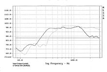
Fig. 2 - Frequency response (magnitude) measurement of drive unit and TL outputs
68:
501:
71:, which transmitted sound to a different location with minimal loss and distortion,
253:
205:
100:
512:
321:
276:
345:
76:
57:
377:
349:
120:
46:
92:
80:
229:
49:
88:
112:
275:
119:
111:
61:
20:
506:
320:
Acoustic transmission lines gained attention in their use within
495:
329:
99:
which use the same principle to produce accurate extended low
259:
The complex loading of the bass drive unit demands specific
525:– description of operation, equation and online calculation
116:
Fig. 1 - Relationship between TL length and wavelength
238:
214:
190:
141:
174:{\displaystyle \ell ={\frac {344}{\,4\times f\,~}}}
498:– Martin J King, developer of TL modeling software
244:
220:
196:
173:
8:
41:is the use of a long duct, which acts as an
252:is the length of the transmission line in
356:, an advocate of TL design, stated that:
237:
213:
189:
164:
154:
148:
140:
16:Acoustic waveguide used to transmit sound
519:2009-10-24) – Application, tips, essays
434:
95:it efficiently to the open air), and
7:
523:Quarter Wave Tube - DiracDelta.co.uk
97:transmission line based loudspeakers
228:is the speed of sound in air at 20°
328:and partners under the brand name
14:
509:– TL projects, history & more
457:. American Institute of Physics.
371:Sound ducts as transmission lines
507:Transmission Line Speakers Pages
336:, and were sold by audiophile
261:Thiele-Small driver parameters
1:
423:Transmission line loudspeaker
316:Transmission line loudspeaker
27:transmission line loudspeaker
560:
313:
204:is the sound frequency in
39:acoustic transmission line
513:Brines Acoustics Articles
272:Discovery and development
503:– TL theory & design
496:Quarterwave loudspeakers
413:Loudspeaker measurement
539:Loudspeaker technology
340:in the United States.
281:
246:
232:in meters/second, and
222:
198:
175:
125:
117:
34:
408:Loudspeaker acoustics
338:Irving M. "Bud" Fried
279:
247:
245:{\displaystyle \ell }
223:
199:
176:
123:
115:
24:
453:Beranek, Leo (1954)
444:imf-electronics.com
236:
212:
188:
139:
221:{\displaystyle 344}
442:Reference speakers
403:Frequency response
310:Loudspeaker design
282:
242:
218:
194:
171:
126:
118:
52:of the electrical
43:acoustic waveguide
35:
544:Audio engineering
197:{\displaystyle f}
169:
167:
108:Design principles
54:transmission line
551:
483:
480:
474:
471:
465:
451:
445:
439:
251:
249:
248:
243:
227:
225:
224:
219:
203:
201:
200:
195:
180:
178:
177:
172:
170:
168:
165:
149:
73:wind instruments
559:
558:
554:
553:
552:
550:
549:
548:
529:
528:
492:
487:
486:
481:
477:
472:
468:
452:
448:
440:
436:
431:
399:
373:
354:Irving M. Fried
318:
312:
307:
274:
234:
233:
210:
209:
186:
185:
153:
137:
136:
110:
64:present in it.
17:
12:
11:
5:
557:
555:
547:
546:
541:
531:
530:
527:
526:
520:
510:
504:
499:
491:
490:External links
488:
485:
484:
475:
466:
463:978-0883184943
446:
433:
432:
430:
427:
426:
425:
420:
415:
410:
405:
398:
395:
394:
393:
390:
386:
372:
369:
364:
363:
314:Main article:
311:
308:
306:
303:
298:Wireless World
273:
270:
241:
217:
193:
182:
181:
163:
160:
157:
152:
147:
144:
109:
106:
15:
13:
10:
9:
6:
4:
3:
2:
556:
545:
542:
540:
537:
536:
534:
524:
521:
518:
514:
511:
508:
505:
502:
500:
497:
494:
493:
489:
479:
476:
470:
467:
464:
460:
456:
450:
447:
443:
438:
435:
428:
424:
421:
419:
418:Speaking tube
416:
414:
411:
409:
406:
404:
401:
400:
396:
391:
387:
383:
382:
381:
379:
370:
368:
362:
359:
358:
357:
355:
351:
347:
341:
339:
335:
331:
327:
323:
317:
309:
304:
302:
300:
299:
294:
290:
287:
278:
271:
269:
265:
262:
257:
255:
239:
231:
215:
207:
191:
161:
158:
155:
150:
145:
142:
135:
134:
133:
130:
122:
114:
107:
105:
102:
98:
94:
90:
86:
82:
78:
74:
70:
69:speaking tube
65:
63:
59:
55:
51:
48:
44:
40:
32:
28:
23:
19:
478:
469:
454:
449:
437:
374:
365:
360:
342:
322:loudspeakers
319:
296:
283:
266:
258:
183:
131:
127:
75:such as the
66:
38:
36:
18:
326:John Wright
31:John Wright
533:Categories
429:References
346:infrasonic
332:and later
206:hertz (Hz)
77:pipe organ
58:wavelength
455:Acoustics
389:transfer.
385:transfer.
378:wavefront
350:subwoofer
240:ℓ
159:×
143:ℓ
517:Archived
397:See also
93:coupling
81:woodwind
47:acoustic
29:pioneer
461:
254:meters
184:where
166:
91:, and
89:timbre
50:analog
344:near-
85:brass
62:sound
459:ISBN
305:Uses
101:bass
83:and
334:TDL
330:IMF
292:see
216:344
151:344
60:of
37:An
535::
352:.
256:.
208:,
79:,
515:(
230:C
192:f
162:f
156:4
146:=
Text is available under the Creative Commons Attribution-ShareAlike License. Additional terms may apply.