267:
the glide path indicated on two main instruments, and the oldest version of ILS-instruments was an instrument of its own used instead. This used two dangling bars, fixed in the middle of the top (localizer indicator) and in the middle of the left side (glide path indicator), and if the aircraft was located on the intended glide path, the dangling bars formed a cross. This is, in theory, however, more difficult to learn—but even for pilots experienced with using such indicators, it added another instrument they needed to focus on. With the indicators added to the artificial horizon (and to the compass), the pilot can theoretically watch the attitude simultaneously with the localizer and glide path.
46:
484:
741:
751:
300:
path was represented by a similar, but horizontal, dangling stick, fixed at one of the sides of the gauge. When the aircraft was located exactly at the ILS-beam (or glide path) the two sticks formed a cross. This interface resembles the flight director, which also forms a cross, but on the artificial horizon. This older ILS instrumentation system was omitted around the same time as jet airliners like
236:
179:
27:
296:
located to the right of localizer beam and to the right if the aircraft is located to the left of the localizer beam. When the arrow is "united" to a straight line, then the aircraft is following the localizer beam. (This second "arrow-indicator" is omitted in modern cockpits, but the main compass is still located below the artificial horizon.)
333:
116:
instruments. An older aircraft without an ILS receiver cannot take advantage of any ILS facilities at any runway, and much more importantly, the most modern aircraft have no use of their ILS instruments at runways which lack ILS facilities. In parts of Africa and Asia large airports may lack any kind
299:
The very first generation of localizer gauges had a different cockpit interface, and were not included in the artificial horizon nor any compass, but at a gauge of its own. The localizer was then represented as a dangling stick hanging from a fixed point at the top of a separate gauge, and the glide
295:
below the artificial horizon. The top and bottom of this arrow "is one unit", which shows current heading. But the middle part of this arrow is moving independently of the aircraft's heading. The middle of that arrow could be described as being "stand alone", and moves to the left if the aircraft is
156:
Localizer (LOC) and glide path (G/P) (a.k.a. glide slope ) carrier frequencies are paired so that the navigation radio automatically tunes the G/S frequency which corresponds to the selected LOC frequency. The LOC signal is in the 110 MHz range while the G/S signal is in the 330 MHz range.
323:
The cockpit ILS indicators are not to be confused with the flight director, which also places vertical and horizontal lines on the artificial horizon. A flight director only shows how the autopilot would fly. If the localizer dot (or arrow) indicate runway is to be found to the left, but the flight
319:
at least below 250 knots (for jet airliners), then by pushing a button marked "APP" or "ILS", then the autopilot presumably will turn and then follow the localizer. The autopilot will then also automatically descend according to the glide path. Normal procedure is to capture the localizer first and
275:
is set to the ILS frequency of that specific runway. If the transmitted localizer beam, which usually, but not always, is directed in the heading of the runway extension (exceptions exist, for instance, in
Innsbruck, Austria and in Macao). If the aircraft is located on this line, the localizer dot
266:
The glide path scale is located to the right of the attitude sphere. On aircraft which have a mechanical gyro compass are both the localizer and glide path indicated as a vertical and a horizontal arrow in the compass as well. But they are essentially read in the same way. On some aircraft is only
147:
The signals' phases at the antenna elements are arranged such that the 150 Hz signal is more prominent (has a greater depth of modulation) at a receiver located to the right of centerline, and the 90 Hz signal is more prominent to the left. The cockpit instrument uses the difference
270:
In modern cockpits, the localizer is seen as a colored dot (usually in the shape of a diamond) at the bottom of the artificial horizon. It does not appear during cruise, but comes up during the descent and approach to the selected runway, provided that the
164:
frequencies range between 108.10 MHz and 111.95 MHz (with the 100 kHz first decimal digit always odd, so 108.10, 108.15, 108.30, etc., are LOC frequencies and are not used for any other purpose).
451:
117:
of transmitting ILS system. Some runways have ILS only in one direction; this can still be used for horizontal centering when landing the opposite direction (with lower precision) and is known as the
640:
291:
In older cockpits, the localizer scale below the artificial horizon is rather short. But in older style cockpit instrumentation, the localizer also appears as an arrow in the
636:
259:
the
Attitude Indicator, but is still a part of this instrument together with the glide path indicator and the cross in the center of the instrument which is called
247:. The localizer is shown on the scale below the attitude gauge, and is in this case looking almost as a small white "^" sign. Both the indicator and its scale are
473:
483:
644:
775:
795:
363:
688:
102:
38:
340:
When the glide path is unserviceable, the localizer element can often be conducted as a separate non-precision approach; or a standalone
320:
then follow the glide path as well. If the angle is too large or the airspeed too high, capturing the localizer may be unsuccessful.
780:
222:
189:
660:
628:
466:
375:
612:
580:
528:
369:
420:
260:
20:
672:
620:
616:
744:
204:
785:
656:
624:
608:
592:
520:
459:
200:
148:
between the modulation strengths of the two received signals to indicate left or right deviation from centerline.
790:
680:
560:
406:
ICAO Abbreviations and Codes (DOC 8400) (Report) (6th ed.). International Civil
Aviation Organization. 2004.
395:
ICAO Abbreviations and Codes (DOC 8400) (Report) (9th ed.). International Civil
Aviation Organization. 2016.
324:
director suggests a right turn, and the runway is not visible, then the pilot in command is having difficulties.
78:
754:
728:
652:
315:
engaged. The angle between the aircraft heading and localizer beam should be less than 30 degrees, and the
140:
signal is transmitted at one tenth of the power with a wider beam to prevent receivers from picking up the
708:
600:
648:
492:
344:
installation without an associated glide path, both are abbreviated as 'LOC' (or 'LLZ' prior to 2007.)
720:
632:
604:
588:
536:
532:
129:
106:
568:
564:
556:
516:
341:
750:
704:
576:
552:
544:
316:
244:
240:
112:
A localizer (like a glide path) requires both a transmitting airport runway system and receiving
284:
on the localizer gauge scale in cockpit. The pilot then knows he or she must adjust the heading
712:
596:
272:
45:
696:
716:
512:
508:
235:
161:
769:
692:
668:
524:
488:
358:
255:
The localizer indicator is (on most aircraft manufactured from the late 1950s) shown
676:
584:
572:
548:
540:
305:
292:
133:
431:
724:
276:
will appear in the middle of the scale. But if the aircraft is located a little
132:
at 90 Hz, the other at 150 Hz. These are transmitted from co-located
700:
301:
312:
141:
26:
311:
The expression "catch the localizer" refers to runway approaches with the
353:
136:
antenna elements. Each antenna transmits a narrow beam. In addition, a
113:
332:
82:
207:. Statements consisting only of original research should be removed.
664:
331:
234:
44:
25:
101:(ILS) for the runway centerline when combined with the vertical
455:
172:
128:
Two signals are transmitted on one of 40 ILS channels. One is
641:
Satellite emergency position-indicating radiobeacon station
109:, although both are parts of aviation navigation systems.
77:
prior to 2007), is a system of horizontal guidance in the
81:, which is used to guide aircraft along the axis of the
196:
499:
415:
413:
637:Emergency position-indicating radiobeacon station
19:"Localizer" redirects here. For other uses, see
467:
8:
280:of the beam, the marker will appear to the
645:Standard frequency and time signal station
474:
460:
452:
223:Learn how and when to remove this message
387:
364:Difference in the depth of modulation
7:
487:
63:instrument landing system localizer
14:
749:
740:
739:
482:
243:(AI), more commonly known as an
177:
97:is the lateral component of the
776:Aeronautical navigation systems
681:Instrument landing system (ILS)
629:Radio direction-finding station
491:and systems in accordance with
376:Simplified directional facility
796:Radio stations and systems ITU
613:Radionavigation mobile station
581:On-board communication station
529:High altitude platform station
430:. January 2008. Archived from
370:Localizer type directional aid
1:
661:Ship's emergency transmitter
621:Radiolocation mobile station
617:Radionavigation land station
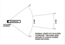
336:Limits of localizer coverage
105:, not to be confused with a
203:the claims made and adding
812:
657:Experimental radio station
625:Radiolocation land station
609:Radiodetermination station
593:Aeronautical earth station
152:Carrier frequency pairings
41:runway 27, Mena, Arkansas)
18:
16:Horizontal guidance system
735:
561:Land mobile earth station
99:instrument landing system
79:instrument landing system
49:Emission patterns of the
781:Aircraft landing systems
729:Emergency locator beacon
653:Radio astronomy station
601:Aircraft earth station
521:Survival craft station
421:"Frequency Allotments"
337:
252:
89:Principle of operation
58:
42:
493:ITU Radio Regulations
335:
238:
48:
29:
721:Multi-satellite link
677:Radar beacon (racon)
633:Radio beacon station
605:Broadcasting station
589:Aeronautical station
537:Mobile earth station
328:Localizer at runways
169:Localizer in cockpit
569:Coast earth station
557:Land mobile station
509:Terrestrial station
342:instrument approach
130:amplitude modulated
33:as component of an
577:Ship earth station
553:Base earth station
545:Land earth station
338:
317:indicated airspeed
253:
245:artificial horizon
241:attitude indicator
188:possibly contains
144:of the main beam.
59:
43:
786:Navigational aids
763:
762:
713:Satellite network
308:were introduced.
233:
232:
225:
190:original research
803:
791:Radio navigation
753:
743:
742:
709:Satellite system
597:Aircraft station
504:
486:
476:
469:
462:
453:
446:
445:
443:
442:
436:
425:
417:
408:
407:
403:
397:
396:
392:
273:navigation radio
228:
221:
217:
214:
208:
205:inline citations
181:
180:
173:
811:
810:
806:
805:
804:
802:
801:
800:
766:
765:
764:
759:
731:
697:Radio altimeter
673:Secondary radar
649:Amateur station
502:
500:
495:
480:
450:
449:
440:
438:
434:
423:
419:
418:
411:
405:
404:
400:
394:
393:
389:
384:
350:
330:
261:flight director
229:
218:
212:
209:
194:
182:
178:
171:
154:
93:In aviation, a
91:
24:
17:
12:
11:
5:
809:
807:
799:
798:
793:
788:
783:
778:
768:
767:
761:
760:
758:
757:
747:
736:
733:
732:
717:Satellite link
715: |
689:ILS glide path
619: |
533:Mobile station
507:
505:
497:
496:
489:Radio stations
481:
479:
478:
471:
464:
456:
448:
447:
409:
398:
386:
385:
383:
380:
379:
378:
373:
367:
361:
356:
349:
346:
329:
326:
231:
230:
185:
183:
176:
170:
167:
153:
150:
90:
87:
15:
13:
10:
9:
6:
4:
3:
2:
808:
797:
794:
792:
789:
787:
784:
782:
779:
777:
774:
773:
771:
756:
752:
748:
746:
738:
737:
734:
730:
727: |
726:
723: |
722:
719: |
718:
714:
711: |
710:
707: |
706:
703: |
702:
699: |
698:
695: |
694:
693:Marker beacon
691: |
690:
687: |
686:
685:ILS localizer
683: |
682:
679: |
678:
675: |
674:
671: |
670:
669:Primary radar
667: |
666:
663: |
662:
659: |
658:
655: |
654:
651: |
650:
647: |
646:
643: |
642:
639: |
638:
635: |
634:
631: |
630:
627: |
626:
623: |
622:
618:
615: |
614:
611: |
610:
607: |
606:
603: |
602:
599: |
598:
595: |
594:
591: |
590:
587: |
586:
583: |
582:
579: |
578:
575: |
574:
571: |
570:
567: |
566:
565:Coast station
563: |
562:
559: |
558:
555: |
554:
551: |
550:
547: |
546:
543: |
542:
539: |
538:
535: |
534:
531: |
530:
527: |
526:
525:Fixed station
523: |
522:
519: |
518:
517:Space station
515: |
514:
513:Earth station
511: |
510:
506:
498:
494:
490:
485:
477:
472:
470:
465:
463:
458:
457:
454:
437:on 2010-08-28
433:
429:
422:
416:
414:
410:
402:
399:
391:
388:
381:
377:
374:
371:
368:
365:
362:
360:
359:Andrew Alford
357:
355:
352:
351:
347:
345:
343:
334:
327:
325:
321:
318:
314:
309:
307:
303:
297:
294:
289:
287:
283:
279:
274:
268:
264:
262:
258:
250:
246:
242:
237:
227:
224:
216:
206:
202:
198:
192:
191:
186:This section
184:
175:
174:
168:
166:
163:
158:
151:
149:
145:
143:
139:
135:
131:
126:
124:
120:
115:
110:
108:
104:
100:
96:
88:
86:
84:
80:
76:
72:
68:
64:
56:
52:
47:
40:
36:
32:
28:
22:
705:Space system
684:
585:Port station
573:Ship station
549:Base station
541:Land station
439:. Retrieved
432:the original
428:NTIA.DOC.gov
427:
401:
390:
339:
322:
310:
298:
293:gyro compass
290:
285:
281:
277:
269:
265:
256:
254:
248:
219:
213:October 2016
210:
187:
159:
155:
146:
137:
134:phased array
127:
122:
118:
111:
98:
94:
92:
74:
70:
66:
65:, or simply
62:
60:
54:
50:
34:
30:
21:Localization
725:Feeder link
123:back course
770:Categories
701:Radiosonde
441:2022-06-26
382:References
302:Boeing 707
197:improve it
142:side lobes
103:glide path
55:glide path
313:autopilot
288:the dot.
201:verifying
119:back beam
95:localizer
67:localizer
51:localizer
31:Localizer
745:Category
354:AN/MRN-1
348:See also
138:clearing
501:desig-
286:towards
195:Please
162:carrier
114:cockpit
107:locator
57:signals
755:Portal
503:nation
83:runway
665:Radar
435:(PDF)
424:(PDF)
372:(LDA)
366:(DDM)
282:right
257:below
249:small
73:, or
306:DC 8
304:and
278:left
160:LOC
53:and
39:KMEZ
239:An
199:by
121:or
75:LLZ
71:LOC
61:An
35:ILS
772::
426:.
412:^
263:.
125:.
85:.
475:e
468:t
461:v
444:.
251:.
226:)
220:(
215:)
211:(
193:.
69:(
37:(
23:.
Text is available under the Creative Commons Attribution-ShareAlike License. Additional terms may apply.