256:
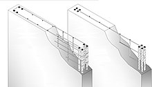
arises whenever a section experiences a flexural or restrained warping stress and its magnitude is dependent on the stiffness of the coupling element. Depending on this stiffness, the performance of a coupled section will fall between that of an ideal uniform element of similar gross plan cross-section and the combined performance of the independent component parts. Another advantage of coupling is that it enhances the overall flexural stiffness dis-proportionally to shear stiffness, resulting in smaller shear deformation.
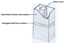
312:. In multi-storey commercial buildings, shear walls form at least one core (Figure 3). From a building services perspective, the shear core houses communal services including stairs, lifts, toilets and service risers. Building serviceability requirements necessitates a proper arrangement of a shear core. From the structural point of view, a shear core could strengthen the building's resistance to lateral loads, i.e., wind load and seismic load, and significantly increase the building safety.
110:
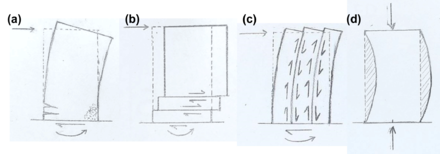
shear, torsional and flexural strains, resulting in a complicated internal stress distribution. In this way, loads are transferred vertically to the building's foundation. Therefore, there are four critical failure mechanisms; as shown in Figure 1. The factors determining the failure mechanism include geometry, loading, material properties, restraint, and construction. Shear walls may also be constructed using light-gauge steel diagonal bracing members tied to collector and ancor points.
124:
247:
walls are vulnerable to buckling failure modes, including Euler in-plane buckling due to axial compression, Euler out-of-plane buckling due to axial compression and lateral torsional buckling due to bending moment. In the design process, structural engineers need to consider all these failure modes to ensure that the wall design is safe under various kinds of possible loading conditions.
20:
190:
326:
294:
99:
372:
Tunnel form construction uses a formwork system to cast slabs and walls as a single pour operation. It is suitable for cellular structures with regular repetition of both horizontal and vertical members. The advantage of this method is that the construction can progress vertically and horizontally at
246:
The slenderness ratio of a wall is defined as a function of the effective height divided by either the effective thickness or the radius of the gyration of the wall section. It is highly related to the slenderness limit that is the cut-off between elements being classed "slender" or "stocky". Slender
255:
In actual structural systems, the shear walls may function as a coupled system instead of isolated walls depending on their arrangements and connections. Two neighboring wall panels can be considered coupled when the interface transfers longitudinal shear to resist the deformation mode. This stress
363:
Jump forming, also known as climbing forming, is a method of construction whereby the walls are cast in discrete lifts. It is a stop-start process with day joints formed at each lift level. Similar to slip forming, jump forming is only efficient for structures with repetition of wall arrangement.
354:
Slip forming is method of concrete placement whereby a moving form is used to create a continuous wall extrusion. This method is very efficient for well-suited structures, such as flanged and core wall systems. A very accurate wall thickness can be achieved but the surface is rough because of the
109:
A shear wall is stiffer in its principal X and Y axes than it is in its Z axis. It is considered as a primary structure which provides relatively stiff resistance to vertical and horizontal forces acting in its plane. Under this combined loading condition, a shear wall develops compatible axial,
336:
Concrete shear walls are reinforced with both horizontal and vertical reinforcement (Figure 4). A reinforcement ratio is defined as the ratio of the gross concrete area for a section taken orthogonal to the reinforcement. Construction codes of practice define maximum and minimum amounts of
77:
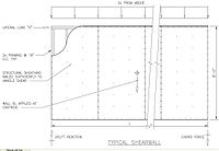
While plywood is the conventional material used in wood (timber) shear walls, advances in technology and modern building methods have produced prefabricated options such as sheet steel and steel-backed shear panels used for narrow walls bracketing an opening that have proven to provide stronger
284:
Hotel or dormitory buildings require many partitions, allowing insertions of shear walls. In these structures, traditional cellular construction (Figure 2) is preferred and a regular wall arrangement with transverse cross walls between rooms and longitudinal spine walls flanking a central
345:
The traditional shuttered lifts method should be used when the total number of walls is small or the arrangement is irregular. In this method, walls are formed one story at one time together with the columns. Although it is slow, this technique may produce a premium finish quality or texture.
274:
432:, and multi-layer models. More recently, fiber-section beam-columns elements have become popular, as they can model most of the global response and failure modes properly, while avoiding sophistications associated with finite element models.
381:
Due to functional requirements, the designer may choose non planar sections like C,L as opposed to the planar sections like rectangular/bar bell sections. Nonplanar sections require 3D analysis and are a research area.
364:
Moreover, it is convenient for adding connections and extrusions at the floor level due to the discrete features. Nevertheless, the inclusion of day joints leaves higher chances for defects and imperfections.
264:
The location of a shear wall significantly affects the building function, such as natural ventilation and daylighting performance. The performance requirements vary for buildings of different functions.
390:
Modeling techniques have been progressively updated during the last two decades, moving from linear static to nonlinear dynamic, enabling more realistic representation of global behavior, and different
395:. Different modeling techniques shear walls span from macro models such as modified beam-column elements, to micro models such as 3D finite element models. An appropriate modeling technique should:
337:
reinforcement as well as the detailing of steel bars. Common construction methods for in-situ reinforced concrete walls include traditional shuttered lifts, slip form, jump form and tunnel form.
23:
A typical timber shear wall consists of braced panels in the wall line, constructed using structural plywood sheathing, specific nailing at the edges, and supporting framing.
507:
58:
shear to shear walls and other vertical elements of the seismic force resisting system. Shear walls are typically made of light framed or braced
456:
517:
392:
233:
171:
200:
551:
149:
55:
145:
82:
215:
134:
546:
211:
153:
138:
105:
Failure mechanisms of shear walls. (a) flexural failure, (b) horizontal shear, (c) vertical shear, (d) buckling.
461:
32:
523:
556:
441:
429:
71:
428:
Different models have been developed over time, including macro-models, vertical line element models,
67:
36:
513:
50:
A shear wall resists loads parallel to the plane of the wall. Collectors, also known as
305:
51:
540:
412:
373:
the same time, thereby increasing the integrity and stability of the structure.
123:
332:
Reinforced concrete shear wall with both horizontal and vertical reinforcement.
304:
A structure of shear walls in the center of a large building—often encasing an
481:
405:
44:
19:
325:
293:
273:
98:
421:
63:
85:
and
International Residential Code govern the design of shear walls.
532:
218:. Statements consisting only of original research should be removed.
324:
292:
272:
59:
40:
482:"Major Techniques for Modeling Shear Walls | FPrimeC Solutions"
183:
117:
207:
280:
Coupled shear wall acting as the partitioning system.
509:
Earthquakes and
Engineers: An International History
62:walls sheathed in shear-resisting material such as
402:Incorporating important materials characteristics
260:Arrangement in buildings with different functions
399:Be capable of predicting the inelastic response
16:A wall intended to withstand the lateral load
8:
408:behavioural feature: Lap splice and Bar Slip
152:. Unsourced material may be challenged and
234:Learn how and when to remove this message
172:Learn how and when to remove this message
97:
18:
473:
35:system that is designed to resist in-
7:
150:adding citations to reliable sources
66:or other structurally rigid panels,
355:abrasion of the form on the walls.
14:
188:
122:
89:Structural design considerations
411:Represent the migration of the
251:Coupling effect of shear walls
94:Loading and failure mechanisms
1:
269:Hotel and dormitory buildings
506:Reitherman, Robert (2012).
214:the claims made and adding
83:International Building Code
81:In many jurisdictions, the
573:
512:. Reston, VA: ASCE Press.
39:lateral forces, typically
33:structurally engineered
552:Earthquake engineering
462:Earthquake engineering
341:Shuttered lifts method
333:
301:
281:
106:
54:members, transfer the
24:
442:Finite element method
430:finite-element models
377:Nonplanar shear walls
328:
300:Shear core structure.
296:
276:
101:
22:
446:Stringer panel model
316:Construction methods
308:or stairwell—form a
289:Commercial buildings
146:improve this section
78:seismic resistance.
436:Methods of analysis
386:Modeling techniques
74:, or steel plates.
68:reinforced concrete
31:is an element of a
417:Tension stiffening
368:Tunnel form method
334:
302:
285:corridor is used.
282:
199:possibly contains
107:
25:
547:Structural system
424:and shear actions
244:
243:
236:
201:original research
182:
181:
174:
114:Slenderness ratio
564:
527:
522:. Archived from
493:
492:
490:
489:
478:
359:Jump form method
350:Slip form method
239:
232:
228:
225:
219:
216:inline citations
192:
191:
184:
177:
170:
166:
163:
157:
126:
118:
572:
571:
567:
566:
565:
563:
562:
561:
537:
536:
520:
505:
502:
497:
496:
487:
485:
480:
479:
475:
470:
453:
438:
420:Interaction of
388:
379:
370:
361:
352:
343:
323:
318:
291:
271:
262:
253:
240:
229:
223:
220:
205:
193:
189:
178:
167:
161:
158:
143:
127:
116:
96:
91:
17:
12:
11:
5:
570:
568:
560:
559:
554:
549:
539:
538:
535:
534:
529:
528:
526:on 2012-07-26.
518:
501:
500:External links
498:
495:
494:
472:
471:
469:
466:
465:
464:
459:
452:
449:
448:
447:
444:
437:
434:
426:
425:
418:
415:
409:
403:
400:
387:
384:
378:
375:
369:
366:
360:
357:
351:
348:
342:
339:
322:
319:
317:
314:
306:elevator shaft
290:
287:
270:
267:
261:
258:
252:
249:
242:
241:
196:
194:
187:
180:
179:
130:
128:
121:
115:
112:
95:
92:
90:
87:
15:
13:
10:
9:
6:
4:
3:
2:
569:
558:
555:
553:
550:
548:
545:
544:
542:
533:
531:
530:
525:
521:
519:9780784410714
515:
511:
510:
504:
503:
499:
483:
477:
474:
467:
463:
460:
458:
455:
454:
450:
445:
443:
440:
439:
435:
433:
431:
423:
419:
416:
414:
410:
407:
404:
401:
398:
397:
396:
394:
393:failure modes
385:
383:
376:
374:
367:
365:
358:
356:
349:
347:
340:
338:
331:
330:Figure 4
327:
320:
315:
313:
311:
307:
299:
298:Figure 3
295:
288:
286:
279:
275:
268:
266:
259:
257:
250:
248:
238:
235:
227:
217:
213:
209:
203:
202:
197:This section
195:
186:
185:
176:
173:
165:
155:
151:
147:
141:
140:
136:
131:This section
129:
125:
120:
119:
113:
111:
104:
103:Figure 1
100:
93:
88:
86:
84:
79:
75:
73:
70:, reinforced
69:
65:
61:
57:
53:
48:
46:
42:
38:
34:
30:
21:
557:Construction
524:the original
508:
486:. Retrieved
484:. 2016-07-29
476:
427:
413:neutral axis
389:
380:
371:
362:
353:
344:
335:
329:
309:
303:
297:
283:
277:
263:
254:
245:
230:
221:
198:
168:
159:
144:Please help
132:
108:
102:
80:
76:
49:
28:
26:
541:Categories
488:2016-07-29
468:References
310:shear core
208:improve it
29:shear wall
457:Hold down
224:July 2024
212:verifying
162:July 2024
133:does not
56:diaphragm
451:See also
406:Simulate
321:Concrete
278:Figure 2
422:flexure
206:Please
154:removed
139:sources
72:masonry
64:plywood
47:loads.
45:seismic
516:
60:wooden
37:plane
514:ISBN
137:any
135:cite
52:drag
43:and
41:wind
210:by
148:by
543::
27:A
491:.
237:)
231:(
226:)
222:(
204:.
175:)
169:(
164:)
160:(
156:.
142:.
Text is available under the Creative Commons Attribution-ShareAlike License. Additional terms may apply.