
A tremie is a watertight pipe, usually of about 250 mm inside diameter (150 to 300 mm), with a conical hopper at its upper end above the water level. It may have a loose plug or a valve at the bottom end. A tremie is usually used to pour concrete underwater in a way that avoids washout of cement from the mix due to turbulent water contact with the concrete while it is flowing. This produces a more reliable strength of the product. Common applications include:
- Caissons, which are the foundations of bridges, among other things, that span bodies of water.
- Pilings.
- Monitoring wells. Builders use tremie methods for materials other than concrete, and for industries other than construction. For example, bentonite slurries for monitoring wells are often emplaced via tremie pipe.
Function
The tremie concrete placement method uses a vertical or nearly vertical pipe, through which concrete is placed by gravity feed below water level.
The lower end of the pipe is kept immersed in fresh concrete so that concrete rising from the bottom displaces the water above it, thus limiting washing out of the cement content of the fresh concrete at the exposed upper surface. The upper end of the tremie pipe is kept above the water level during the pour and is provided with a conical hopper for batch loading, or concrete may be pumped into the top of the tremie pipe. Concrete must be poured at a rate which avoids setting in the tremie. Admixtures may be used to control setting time, slump and workability. Vibration and jerking of the pipe may be applied to encourage slumping and levelling of the upper surface of the pour, and the tremie may need to be raised occasionally during the pour so that the bottom end is not too deeply embedded, but the pipe must not be moved sufficiently to break clear of the mound and expose the bottom opening to the water, as this would allow washout of cement.
Structure
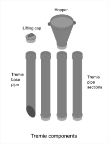
The tremie pipe is usually made up of short pipe sections of about 250 mm inside diameter joined by screw thread with O-ring seal, or by gasketed flanges, so that the length can be adjusted during the pour without getting the top of the pipe below the water or removing the bottom end from below the surface of the poured concrete. To facilitate management of pipe length it may be built up from 1m to 3.5m sections. The tremie is often supported by a working platform above the water level, with a conical hopper at its upper end above the water level.
Various types of foot valve may be used to shut off flow while moving the pipe when pouring small volumes in disjoint areas, where it is impracticable to maintain immersion of the nozzle in the fresh concrete, as in repair work. One type is a rubber sleeve inside a section of the pipe which can be pneumatically inflated to occlude the bore over a short distance. Another uses a hydraulically operated plate moved across the flow.
The tremie can be inclined to control flow rate when working in small or shallow volumes, where it may be impossible to keep the nozzle adequately immersed. A flexible hose section at the nozzle can facilitate accurate placement by a diver.
A foam rubber 'pig' or a plug made from cement bags may be used to plug the pipe while introducing the first batch of concrete.
Placement
To start placement, the tremie pipe is first lowered into position. Air and water must be kept out of the tremie during placement by keeping the pipe full of concrete at all times. This is facilitated if the hopper capacity is at least equal to the volume of the pipe. When initially charging the tremie, a wad of empty cement bags or a foam rubber plug known as a pig may be stuffed into the pipe to keep the flow under control while the first concrete forces the plug down the pipe and displaces the water. The pig will be pushed out of the bottom end of the pipe and will float to the surface. The discharge opening must be kept well immersed in the placed concrete, allowing flow from within the placement. 1.5 metres (5 ft) of embedment should be maintained as a minimum if possible. This can be measured by finding the level of the concrete surface below the top of the pipe with a weighted tape and subtracting from the known length of the tremie. It is critically important to concrete quality that the tremie discharge remains well embedded in the concrete. As the pour progresses, if flow slows or stops, the discharge opening is raised so that the head in the pipe can maintain flow. Continuous flow is desirable if possible. The tremie should be raised at about the same rate that the concrete level rises, and the discharge end of the pipe must remain embedded in the fresh concrete deeply enough to prevent water from flowing into the pipe and causing dilution or segregation of the concrete.
If it is necessary to move the tremie laterally, it is better to lift it out vertically, plug it and start a new pour at the new position than to drag it sideways through freshly placed concrete. If the area of the pour is too large to manage from a single point, it is better to use several tremies in parallel than to shift a single tremie around. A spacing between tremies of between 3.5–5 m (11–16 ft), and a distance of about 2.5 m (8 ft) from the formwork has been recommended. The risk of segregation and uneven setting can be minimised by providing a continuous flow of concrete through all the tremies to maintain a moderately even top surface.
Concrete
Concrete for tremie placement should be fluid but resistant to segregation, with a very high slump of about 150 to 200 mm (6 to 8 in), typically achieved by adding superplasticizers.
References
- ^ "Concrete Pumping Products - Tremie Pipes". we-couplings.com. Anderton, Lancashire: W.E. Couplings Ltd. Retrieved 1 June 2017.
- ^ "How Tremie Pipes Ensuring Quality in Underwater Concrete Placement Construction?". www.drillmastergroup.com. Retrieved 18 September 2024.
- Nielsen, David, ed. (1991). Practical handbook of ground-water [sic] monitoring. CRC Press LLC. p. 321. ISBN 0-87371-124-6.
In wells more than about 50 feet deep, granular bentonite may be mixed with water and conveyed through a tremie pipe from the surface directly to its intended depth in the annulus. Pelletized bentonite is not effectively installed through tremie pipes.
- Beckhaus, Karsten; Bartho, Admiraal; Böhle, Björn; Boilesen, Jesper; Boutz, Michael (2016). "EFFC/DFI Best Practice Guide to Tremie Concrete for Deep Foundations" (PDF). Deep Foundation Institute proceedings. European Federation of Foundation Contractors / Deep Foundation Institute. Retrieved 22 June 2020.
guidance on the characteristic performance of fresh concrete and its method of placement using tremie methods in bored piles and diaphragm walls, allowing construction of high quality elements
- Bhattacharya, Dhrubajyoti. Analysis of tremie technique in concreting of bottom plug of wells (PDF). Retrieved 1 June 2017.
- ^ Khayat, Kamal H.; Gerwick Jr, Ben C.; T. Hester, Weston (April 1993). "Concrete placement with inclined tremie for small underwater repairs". ACI Concrete International. 15 (4): 49–56.
- ^ "Method of underwater concreting - Tremie method". Civil Engineers Today. 22 February 2009. Retrieved 1 June 2017.
- Suryakanta (6 April 2015). "How concreting is done under water by tremie method?". Concrete technology. Civilblog.org. Retrieved 1 June 2017.
| History | |
|---|---|
| Composition | |
| Production | |
| Construction | |
| Science | |
| Types | |
| Applications | |
| Organizations | |
| Standards | |
| See also | |